ES Range Product Manual
Version 2.9
© Copyright Brainboxes Limited 2013
Page 20 of 66
6. RS-422/485 Settings (ES-320/ES-313/ES-346/ES-
842/ES-357/ES-031/ES-042)
The factory default setting for the ES devices is RS-422 full duplex.
DTR/DSR Handshaking is not available on 422/485 ports.
The RS-485 standard talks about the differential pair as ‘Data A’ and ‘Data B’ but line driver chip
manufacturers use the labels ‘Data+’ and ‘Data-’. ‘Data A’ is the inverting pin ‘Data-’ and ‘Data B’ is
the non-inverting pin ‘Data+’
If you can’t get the connection to work it may be because you have mistakenly connected the lines the
wrong way round.
The RS-422 Standard
The RS-422 standard defines a serial communications standard. RS-422 is a high speed and/or long
distance data transmission. Each signal is carried by a pair of wires and is thus a differential data
transmission system. Over distances up to 40 feet the maximum data rate is 10 Megabits per second,
and for distances up to 4000 feet the maximum data rate is 100 Kilobytes per second. A 120-Ohm
resistor should be used to terminate the receiving end of the line. It is generally used between one
transmitter receiver pair to ONLY one other transmitter receiver pair, but each output can drive up to
10 receivers.
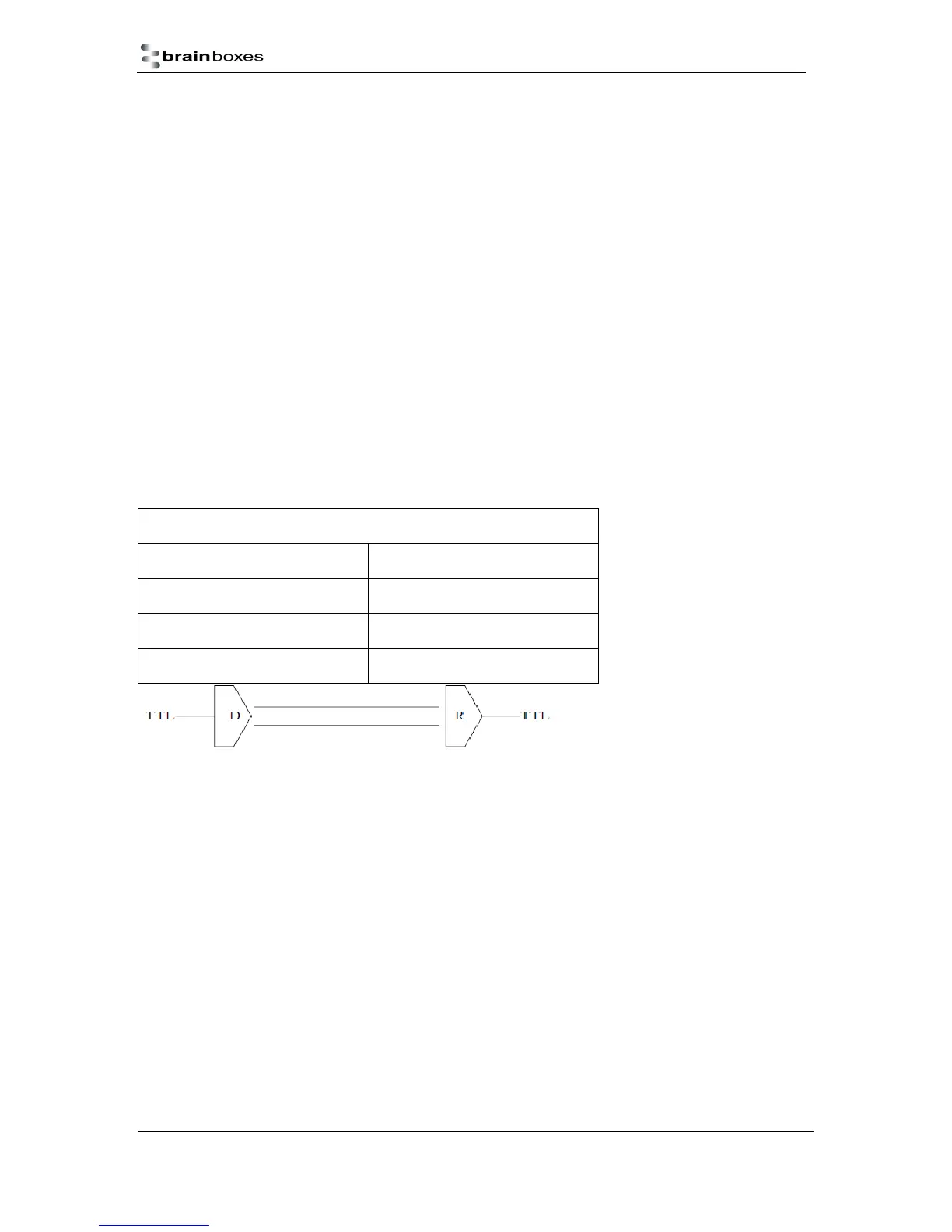
RS-422 Standard -1 Driver up to 10 Receivers
Line Length Max Data Rate
40 Feet = 12m 10 Mbits/sec
400 Feet = 122m 1 Mbits/sec
4000 Feet = 1219m 100 Kbits/sec
RS-422 Operation
Generally, in RS-422 systems all 8 signal lines from the 9 pin D connector participate in the data
transfer sequence, thus 4 twisted pair cables are used. One twisted pair carries the TXD data
outwards, one pair brings the RXD data inward, another pair carries the RTS handshake outwards
and the fourth pair brings the CTS handshake inwards. There is no need to carry the ground from one
device to another. This RS-422 arrangement allows data to be transmitted and received
simultaneously since each signal has its own data cable pair. In addition, the receiver can set RTS
true so telling the transmitter on its CTS input that the receiver is ready to accept data. In this way, no
data will ever be transmitted when the receiver is unable to accept it, due to a full input buffer etc. And
so no data will be lost.
RS-422 Full Duplex Mode
This mode is generally used between one transmitter / receiver to only one other transmitter /
receiver, but it is possible for each output to drive up to 10 receivers.
Generally, in RS-422 systems, all 8 signal lines from the 9 pin D connector or terminal block
participate in the data transfer sequence. Thus 4 twisted pair cables are used. One twisted pair
carries the TXD data outwards, one pair brings the RXD data inward, another pair carries the RTS
handshaking signal outwards, and the fourth pair brings the CTS handshaking signal inwards. There
is no need to carry the ground from one device to another.