ES Range Product Manual
Version 2.9
© Copyright Brainboxes Limited 2013
Page 28 of 66
To access the headers, the case of the ES-313 or ES-320 needs to be opened.
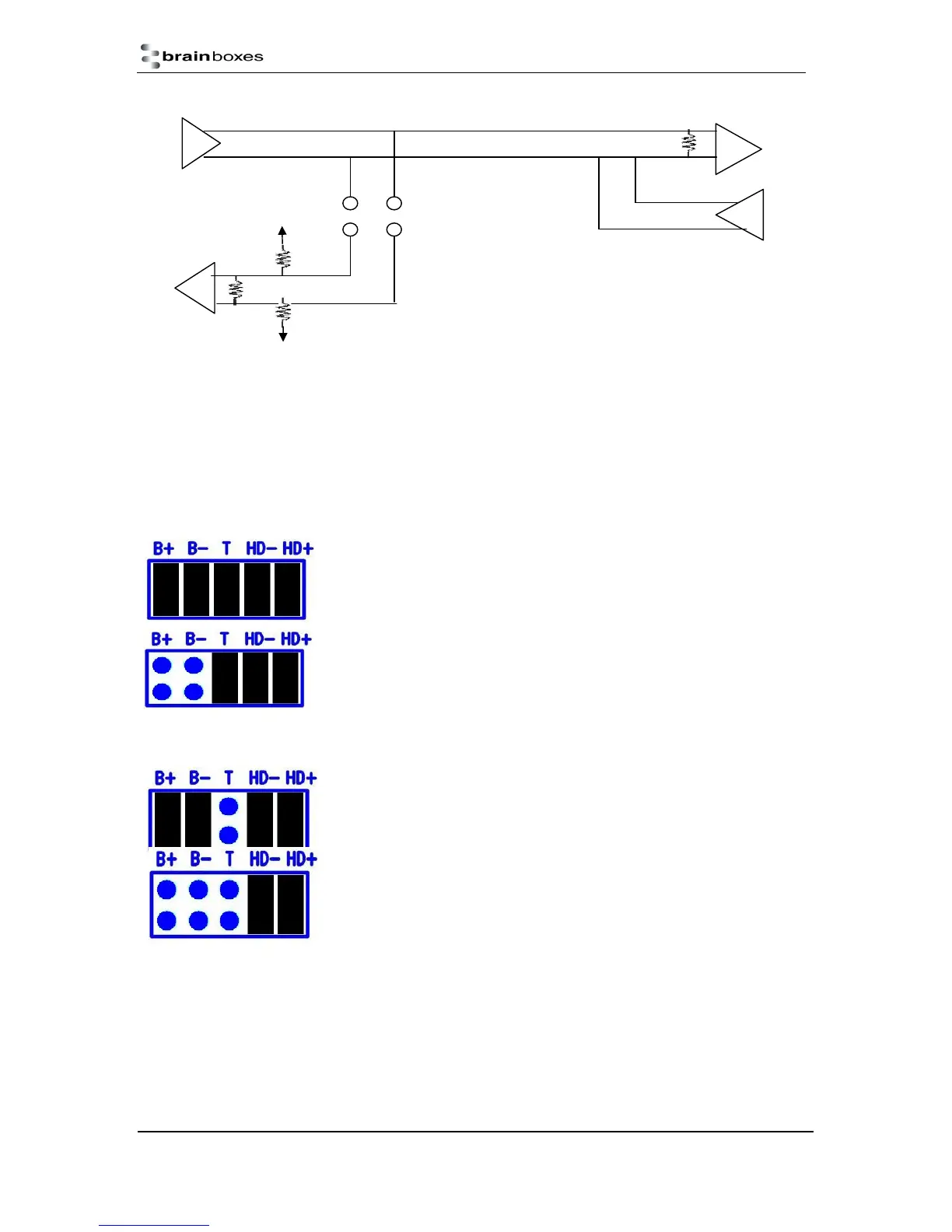
Jumpers can be placed vertically across any of the 5 sets of pins explained as thus below:-
B+ and B- = are bias resistors.
T = Termination resistor
HD+ and HD- = are half duplex pins.
So the possible configurations are:
Half-duplex point-to-point link, when no other biasing is present:
And when biasing is already present somewhere.
For a half-duplex multi-drop bus, if the device is at the end of the bus then use the same jumper
configurations as for a half-duplex point-to-point link, above.
For a half-duplex multi-drop bus, where the device is not at the end of the
bus but somewhere in the middle.
Or depending on whether biasing is already presents somewhere.
T
B+
3V3
B-
GND
H+ H-