2 - 4 Power Wiring2 - 4 Power Wiring
90 250 VAC or
11 26 VAC / VDC
~
~
Figure 2.6 Power Supply ConnectionsFigure 2.6 Power Supply Connections
1
2
L
N
7
8
L
N
P41
P91
Fuse
2A/250VAC
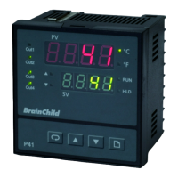
2-5 Sensor Input Wiring2-5 Sensor Input Wiring
18 4
19 5
20 6
P41
P91
PTA
TC+, V+
PTB, mA+
TC+, V+
PTB, mA+
TC-, V-
PTB, mA-
TC-, V-
PTB, mA-
B
B
A
RTD
_
_
+
+
V
_
+
TC V mA RTD
Figure 2.7 Sensor Input WiringFigure 2.7 Sensor Input Wiring
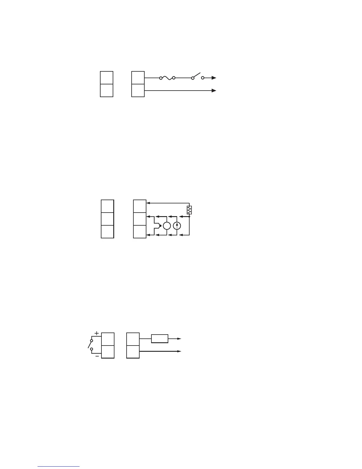
2-6 Control Output Wiring2-6 Control Output Wiring
3
4
P41
P91
9
10
LOAD
120V/240VAC
Mains Supply
120V/240VAC
Mains Supply
Figure 2.8
Output 1 Relay or Triac (SSR) to Drive Load
Figure 2.8
Output
1 Relay or Triac (SSR) to Drive Load
UM0P411A
36