SERIES 70 ELECTRIC ACTUATOR
Installation, Operation, and Maintenance Manual
19 of 48
© 2022 BRAY INTERNATIONAL, INC. ALL RIGHTS RESERVED. BRAY.COM
The Information contained herein shall not be copied, transferred, conveyed, or displayed in any manner
that would violate its proprietary nature without the express written permission of Bray International, Inc.
ACTUATION
Manual Operation
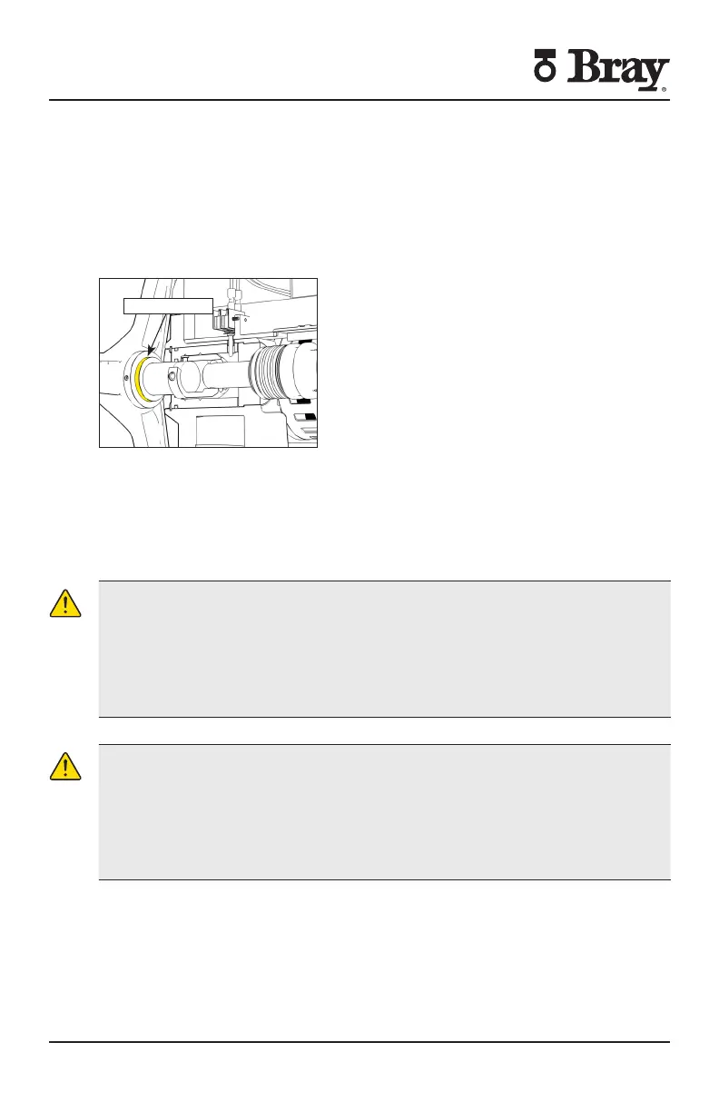
The manual override operates similar to a watch adjusting knob To engage the
manual override simply pull the handwheel to its outermost position A yellow stripe
is revealed to visually indicate manual override engagement as shown in Figure
The two handwheel positions engaged and disengaged are held in place with the
use of spring plungers The handwheel remains in position until physically moved
Yellow Stripe
Figure - Handwheel is engaged revealing the yellow stripe
Once the manual override is engaged rotating the handwheel in the clockwise
direction will rotate the output shaft in the clockwise (close) direction and vice-
versa
To disengage the manual override the handwheel needs to be pushed towards the
actuator until the ‘yellow stripe’ is hidden
CAUTION
A label on the handwheel hub warns users not to exceed a specific ‘rim pull’ force
for each size of actuator
If the ‘rim pull’ force is exceeded the roll pin securing the handwheel onto the
manual override shaft is designed to shear thus preventing serious internal gearing
damage
Remote Operation
CAUTION
1. Verify that the main electric power supplied to the actuator is in compliance with
the specifications on the actuator label.
2. Engaging the handwheel before or during the application of a supply voltage
will prevent the actuator motor from operating.
3. If torque switches are installed in the actuator, an over-torque condition will
prevent the actuator motor from operating in the direction of fault.

 Loading...


