SERIES 70 ELECTRIC ACTUATOR
Installation, Operation, and Maintenance Manual
27 of 48
© 2022 BRAY INTERNATIONAL, INC. ALL RIGHTS RESERVED. BRAY.COM
The Information contained herein shall not be copied, transferred, conveyed, or displayed in any manner
that would violate its proprietary nature without the express written permission of Bray International, Inc.
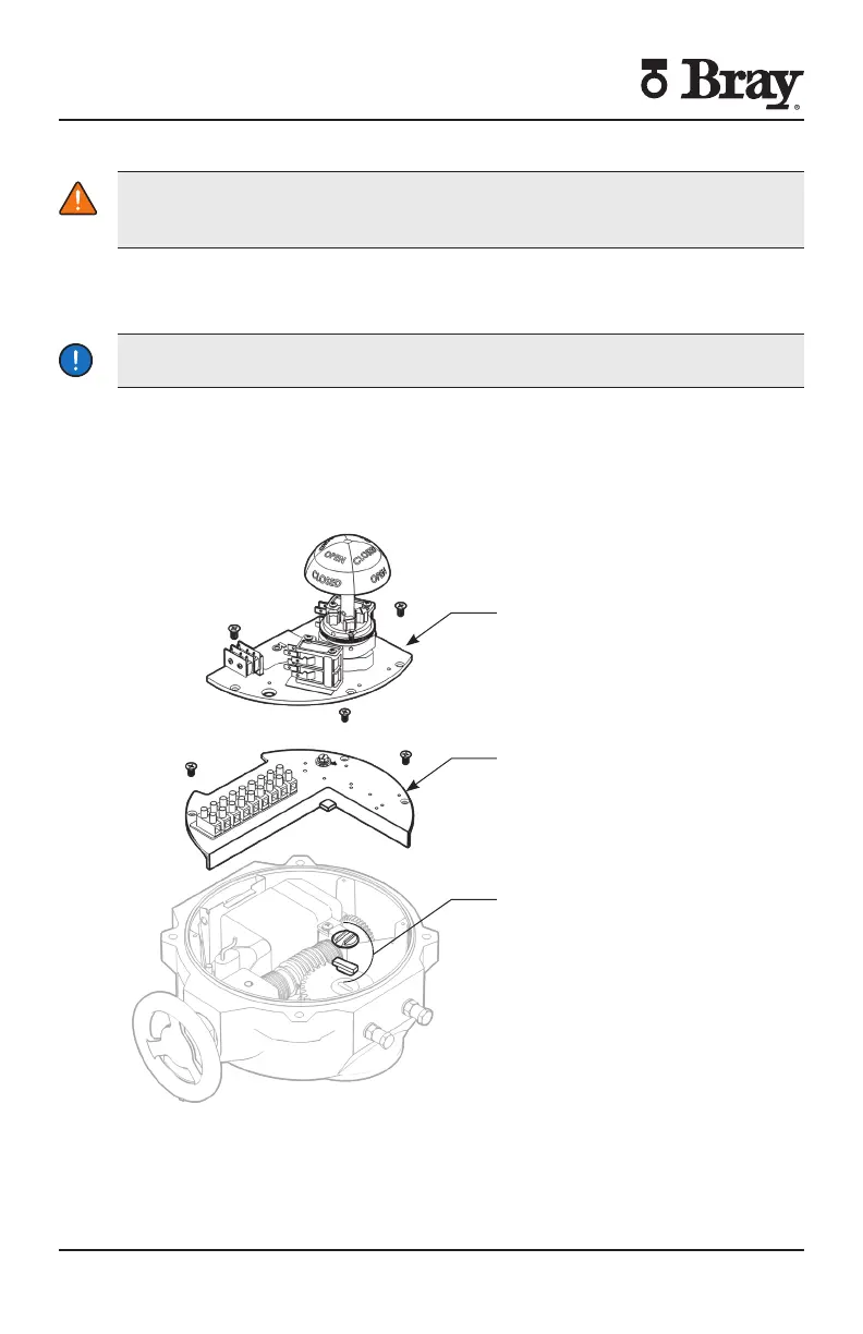
DISASSEMBLY AND ASSEMBLY
WARNING
Turn o all power and lockouttag out service panel before installing or modifying
any electrical wiring
1. Disconnect external wiring from terminals.
2. Disconnect motor wires from the main terminal strip (motor neutral, open, and
close)
NOTICE
Removal of switch plate with torque switches will void warranty
3. To remove the switch plate:
a Follow after disconnecting external wires and motor wires
b Unscrew the seven Phillips head mounting screws
c Lift the switch plate(s) out as an assembly with the indicator shaft attached
d NOTE Do not misplace shaft coupler insert or mounting screws
Switchplate Fixed
Removable Switchplate
Oldham Coupler
Figure S Actuator Size E E E – switch plate removed

 Loading...


