SERIES 70 ELECTRIC ACTUATOR
Installation, Operation, and Maintenance Manual
41 of 48
© 2022 BRAY INTERNATIONAL, INC. ALL RIGHTS RESERVED. BRAY.COM
The Information contained herein shall not be copied, transferred, conveyed, or displayed in any manner
that would violate its proprietary nature without the express written permission of Bray International, Inc.
NOTES
Euro receptacles use AWG wire rated at V Amp Pin configuration
interfaces with European standards
Mini Receptacles use AWG wire rated at V Amp Pin configuration
conforms to ANSI BM
Factory will need wiring diagram drawing number and model of the existing unit
if it is to be retrofit with receptacles New wiring diagram will be provided based
upon this information
Some configurations may limit use of receptacles due to number of wires
entering through the conduit
External Signal Feedback Potentiometer
Potentiometers are a field or factory installable option for continuous duty
actuators Actuators which are not continuous duty do not have a pot gear fitted
on their indicator shafts and must be fitted with a new indicator shaft in the factory
S actuators fitted with electronics for modulating applications already fit a
potentiometer and cannot fit a second In this case retransmission of position is
provided through the modulating electronics package
Feedback Potentiometer Kit
Potentiometer Assembly
Cross Drive Pan Head Screws (Qty)
Internal Lockwashers (Qty)
-pole Terminal Strip
Terminal Strip Marker
Wiring Diagram
Tools Required
Screwdriver [ mm] tip flat blade
Screwdriver No Phillips
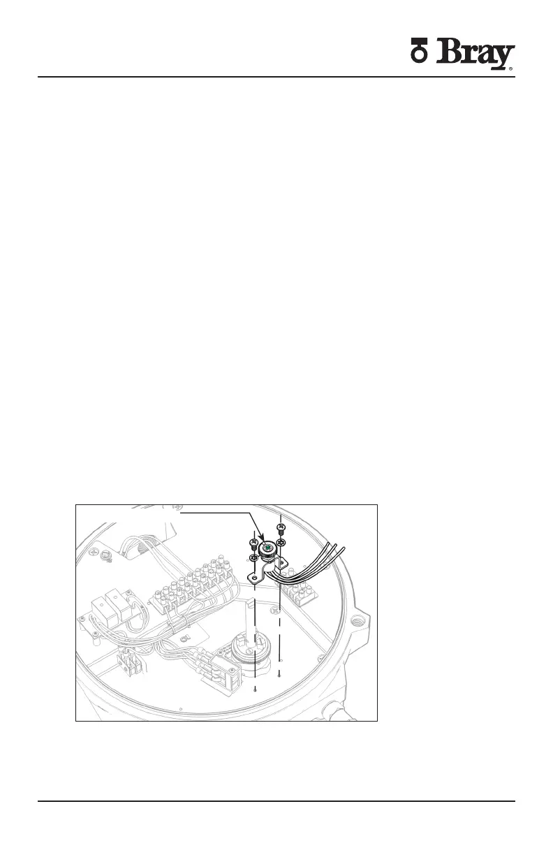
Raised Green Rib
Figure S Potentiometer installation
Orient the actuator in the full open (counter clockwise) position

 Loading...


