SERIES 70 ELECTRIC ACTUATOR
Installation, Operation, and Maintenance Manual
21 of 48
© 2022 BRAY INTERNATIONAL, INC. ALL RIGHTS RESERVED. BRAY.COM
The Information contained herein shall not be copied, transferred, conveyed, or displayed in any manner
that would violate its proprietary nature without the express written permission of Bray International, Inc.
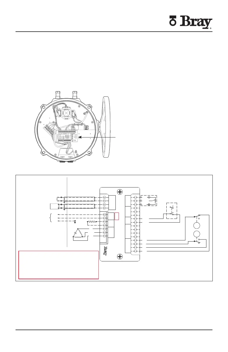
Servo NXT
To control the actuator remotely from a process controller in a modulating
application user must apply the proper supply voltage and the configured control
signal to the Servo NXT electronics package The control signal may be applied
locally from a hand-held signal generator or remotely from a process controller
For more information please refer to the S Servo NXT Manual This manual is
available on the company website (braycom)
Servo NXT
Figure - S with Servo NXT
Figure - Sample field wiring diagram for Series actuator with Servo NXT
Actuator specific wiring diagram located inside actuator cover
Please refer to the rd Digit of the serial number
for Servo NXT hardware version which is located
on the nameplate axed to the side of the
controller
All units up to and including Version G the live and
neutral as shown
Version H and above live and neutral will be
swapped
Field Wiring Actuator
FEEDBACK
POTENTIOMETER
WHITE
ORANGE
GREY
YELLOW
YELLOW
OVERRIDE SW
N.C.
N.O.
N.C.
N.C.
N.O.
N.O.
N.C.
N.O.
COM
COM
COM
COM
BLUE
BLUE
RED
RED
OPEN
CLOSE
GREEN
CAM
RED
CAM
COM
INPUT+
INPUT–
OUTPUT+
OUTPUT–
NEUTRAL
LIVE
NEUTRAL
CLOSE
LIVE
NEUTRAL
OPEN
WIPER
POWER
COM
CLOSE
COM
COM1
COM2
CLOSE
OPEN
COM1
COM2
CLOSE
OPEN
HW
OPEN
LIMIT SW
MOTOR
COMMAND
INPUT
POWER
HEATER
HAND
WHEEL
CTRL BOX
FB POT
TORQUE SW
RED
YELLOW
OR BLACK
BLUE
HEATER
(OPTIONAL)
MOTOR
O
N
C
SHIELDED CABLE
OUTGOING FEEDBACK SIGNAL (SHIELDED)
INCOMING COMMAND SIGNAL
(SEE NOTES 5–7)
(SEE NOTES 6–8)
LOAD DEVICE
NOT TO EXCEED
400 OHMS
(4–20mA CONFIGURATION)
SINGLE PHASE
POWER SUPPLY
NEUTRAL
LIVE
GROUND
POSITION
FEEDBACK
DEVICE

 Loading...


