SERIES 70 ELECTRIC ACTUATOR
Installation, Operation, and Maintenance Manual
25 of 48
© 2022 BRAY INTERNATIONAL, INC. ALL RIGHTS RESERVED. BRAY.COM
The Information contained herein shall not be copied, transferred, conveyed, or displayed in any manner
that would violate its proprietary nature without the express written permission of Bray International, Inc.
6. Manually operate the actuator counterclockwise until the valve reaches the
desired ‘open’ position.
7. Loosen the cam locking screw.
8. Rotate the green cam adjustment knob until the green cam lobe activates
(depresses) the ‘open’ switch from a counterclockwise direction.
9. Tighten the cam locking screw.
10. Place the indicator rotor back on the indicator shaft.
Setting Mechanical Travel Stops
NOTICE
If the unit came assembled to a valve the stops have been factory-set and DO NOT
need adjustment
Mechanical travel stops are designed to prevent over travel while manually operating
the actuator They are not designed to stop the electric motor
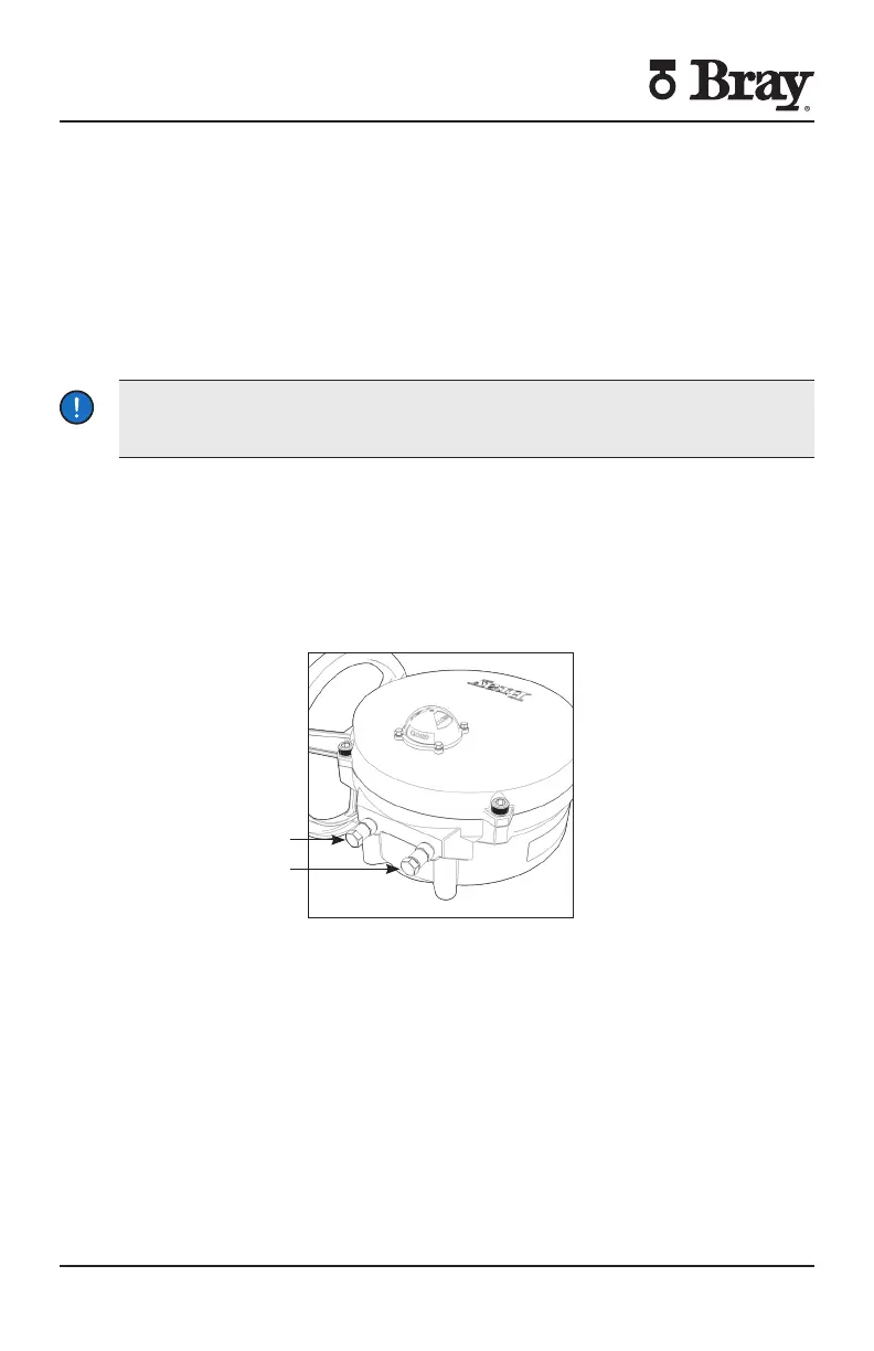
Mechanical travel stops are located outside of the actuator base for easy
readjustment Stainless steel lock nuts with O-ring seals hold the travel stops
securely in place Travel stop spacers are used to ensure that travel stop bolts are
not engaged to where they could limit to electrical operation
NOTE Actuator Size does not use travel stop spacers
Open Travel Stop
Closed Travel Stop
Figure Mechanical Travel Stops (CW Close)
Follow the steps below to set the mechanical travels stops
1. Manually drive the actuator to the ‘closed’ position.
2. Once the actuator is in the ‘closed’ position, rotate the handwheel clockwise:
turn for Actuator Size E E E
turn for Actuator Size E E E
turn for Actuator Size
turns for Actuator Size
3. Adjust the ‘closed’ travel stop bolt until the travel stop spacer is fully engaged or
the travel stop bolt contacts the output segment gear.

 Loading...


