SERIES 70 ELECTRIC ACTUATOR
Installation, Operation, and Maintenance Manual
14 of 48
© 2022 BRAY INTERNATIONAL, INC. ALL RIGHTS RESERVED. BRAY.COM
The Information contained herein shall not be copied, transferred, conveyed, or displayed in any manner
that would violate its proprietary nature without the express written permission of Bray International, Inc.
1
9
7
8
6
21
20
19
13
16
18
17
15
14
12
11
10
4
3
2
13
14
5
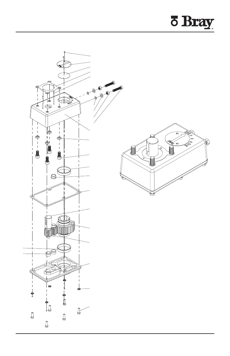
SERIES 70, SIZE -180
3: 1 GEAR BOX
EXPLODED VIEW
ITEM NO.
1
FASTENING SCREW
2
3
POSITION INDICATOR GASKET
4
5
DOWEL PIN
6
O-RING
7
8
NUT,HEX
9
BOLT,HEX HD
10
COVER
11
WASHER, CONICAL
12
ACTUATOR/GEAR BOX FASTENING SCREW
13
14
15
COVER GASKET
16
INPUT GEAR
17
OUTPUT GEAR
18
IDLER GEAR
19
COVER
20
LOCK WASHER
21
BASE FASTENING SCREW
BUSA
BUSA Steven Ospina
10/21/2013
1
Series – Size – Gear Box Exploded View

 Loading...


