SERIES 70 ELECTRIC ACTUATOR
Installation, Operation, and Maintenance Manual
40 of 48
© 2022 BRAY INTERNATIONAL, INC. ALL RIGHTS RESERVED. BRAY.COM
The Information contained herein shall not be copied, transferred, conveyed, or displayed in any manner
that would violate its proprietary nature without the express written permission of Bray International, Inc.
For Actuator Size E - – Place the socket head shoulder bolt through the
spinner handle and screw it firmly into the handwheel rim
Receptacles (Quick Connectors)
Bray oers plug-in receptacles as a field or factory option for quick and easy field
wiring of Series actuators Cord sets to fit these connectors can also be ordered
in several lengths
Unless otherwise specified power receptacles will be -pin mini style standard duty
with a black anodized aluminum finish They conform to ANSI BM except in
wire color Euro receptacles will be used for low power instrument and signal cable
since they can be supplied shielded
Wiring diagrams for plug-in receptacles for either the Bray Series or the local
control station will be provided as a separate diagram Units ordered with pin
connector receptacles factory installed are wired and tested
Receptacle Kit
Receptacle(s) male pin and male thread NPT [M] in the quantity style
and number of pins ordered
Reducing bushing ¾ to NPT [M to M] for installation in Actuator Sizes
E - and control stations
Wiring Diagram
Tools Required
Screwdriver [ mm] tip flat blade
Wrench [mm]
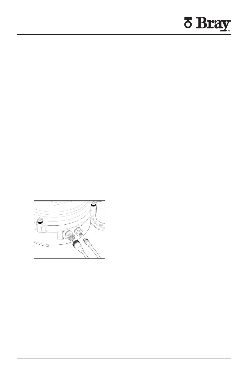
Figure S with -pin receptacle and corresponding cord set
Receptacles (Quick Connectors) Installation Procedure
Screw the receptacle into the actuator conduit entry using Teflon tape or similar
Wire to the terminal strip according to the wiring diagram or the field wiring
requirements

 Loading...


