SERIES 70 ELECTRIC ACTUATOR
Installation, Operation, and Maintenance Manual
20 of 48
© 2022 BRAY INTERNATIONAL, INC. ALL RIGHTS RESERVED. BRAY.COM
The Information contained herein shall not be copied, transferred, conveyed, or displayed in any manner
that would violate its proprietary nature without the express written permission of Bray International, Inc.
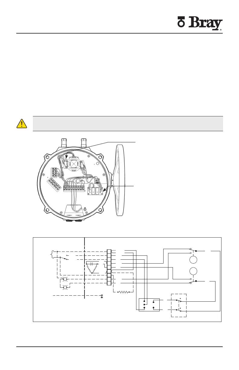
S OnO Actuator with Interposing Relay Board (IRB)
The back feeding of one actuator by another one wired in parallel is eliminated by
using the IRB If actuator is running Open and customer switches “instantaneously”
to run Closed the Open relay will take time to ‘drop-out’ and the Close relay will
take time to ‘pull-in’ this time lapse is ~ ms The time delay provided by the IRB
will protect the switches and gears from the controller’s instantaneous command
signal reversal Current draws and field wirings are not aected by adding IRB
S VAC IRB auxiliary switch heater and torque switch option are UL certified
units
NOTE The host controller should use a one second time delay for command signal
reversal
CAUTION
Apply voltage to only one direction terminal at a time
Auxiliary Switches
IRB
Interposing Relay Board
Figure - S with IRB
SINGLE PHASE
POWER SUPPLY
GROUND
N
L
OPEN
BLUE
CLOSE
OPEN
CLOSE
(SEE NOTE 5)
FOR HEATER OPTION ONLY
RED
YELLOW OR
BLACK
O
C
N
MOTOR
YELLOW
YELLOW
RED
RED
RED
RED
BLUE
OVERRIDE SW
CLOSE
OPEN
RED
HEATER (OPTIONAL)
BLUE
BLUE
BLUE
BLUE
GREEN
CAM
RED
CAM
N.C.
COM
N.O.
N.C.
COM
N.O.
OPEN
CLOSE
COM
COM
N.C.
N.O.
N.C.
N.O.
CL
OP
N
MC
MO
INTERPOSING RELAY
1
2
3
4
5
6
7
8
9
Actuator shown in closed position
Figure - Sample field wiring diagram for Series actuator with IRB
Actuator specific wiring diagram located inside actuator cover
Field Wiring Actuator

 Loading...


