SERIES 70 ELECTRIC ACTUATOR
Installation, Operation, and Maintenance Manual
23 of 48
© 2022 BRAY INTERNATIONAL, INC. ALL RIGHTS RESERVED. BRAY.COM
The Information contained herein shall not be copied, transferred, conveyed, or displayed in any manner
that would violate its proprietary nature without the express written permission of Bray International, Inc.
Wiring the Actuator
WARNING
Turn o all power and lockouttag out service panel before installing or modifying
any electrical wiring
1. Take the actuator cover o. The cover should be kept on hand for reference.
2. Wire the actuator as per the wiring diagram attached to the inside of the
actuator cover.
NOTICE
1. Power and control wiring should use separate conduit entries.
2. A minimum of 18 AWG wire is recommended for all field wiring.
3. Terminals directly mounted on the actuator switch plate accept wire sizes
ranging from 14 to 22 AWG.
4. Terminals of internally mounted electronics modules accept wire sizes ranging
from 14 to 24 AWG.
5. The conduit connections must be properly sealed to maintain the weatherproof
integrity of the actuator enclosure.
Setting Travel Limit Switches
NOTICE
If the unit came assembled to a valve the switches have been factory-set and DO
NOT need adjustment
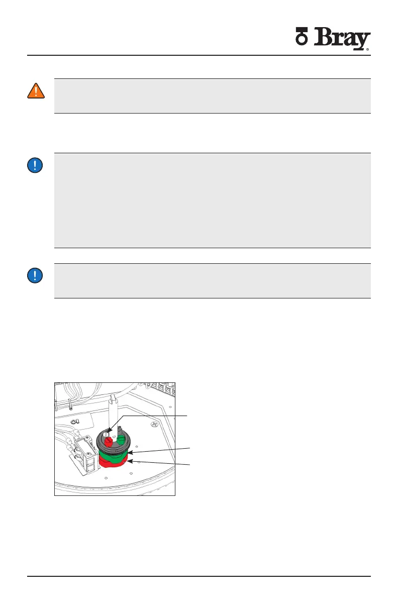
Bray uses its patented cam design along with two SPDT mechanical switches to set
the ‘Open’ and ‘Closed’ position of the valve The green cam actuates the ‘open’
switch when the actuator reaches the ‘open’ position Similarly the red cam actuates
the ‘closed’ switch when the actuator reaches the ‘closed’ position
Standard factory setting of the travel limit switches allows travel between open
and close positions Cams for each switch are adjustable for applications where less
than -degree travel is desired between the open and closed positions
Cam Locking Screw
Figure Two SPDT Travel Limit Switches
Follow the steps below to adjust the travel limit cams
NOTE For Actuator Size ignore steps and
Green - Open
Red - Closed

 Loading...


