SERIES 70 ELECTRIC ACTUATOR
Installation, Operation, and Maintenance Manual
24 of 48
© 2022 BRAY INTERNATIONAL, INC. ALL RIGHTS RESERVED. BRAY.COM
The Information contained herein shall not be copied, transferred, conveyed, or displayed in any manner
that would violate its proprietary nature without the express written permission of Bray International, Inc.
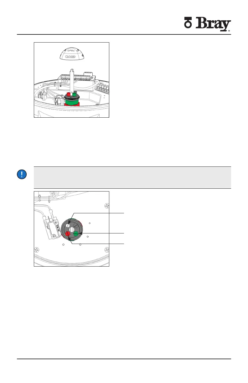
Figure Indicator rotor pulled up from the indicator shaft
1. Remove the indicator rotor by pulling away from the indicator shaft as shown in
Figure 7.
2. Manually operate the actuator clockwise until the valve reaches the desired
‘closed’ position.
3. Loosen the cam locking screw shown in Figure 6.
NOTICE
Cam locking screw must be slackened before cam adjustments and re-tightened
after cam adjustments
Figure Top view of the indicator shaft
NOTE It is possible that the rotation of one cam will move the other cam If this
occurs hold the other knobs or cams during adjustment
4. Rotate the red cam adjustment knob by hand or with a flat head screwdriver
until the red cam lobe just activates (depresses) the ‘closed’ switch from a
clockwise direction.
NOTE: If fixed auxiliary switches are installed, the auxiliary cam will activate prior to
the main cam.
5. Tighten the cam locking screw.
Cam Locking Screw
Green Cam Adjustment Screw
Red Cam Adjustment Screw

 Loading...


