4.3 Operation of the pump
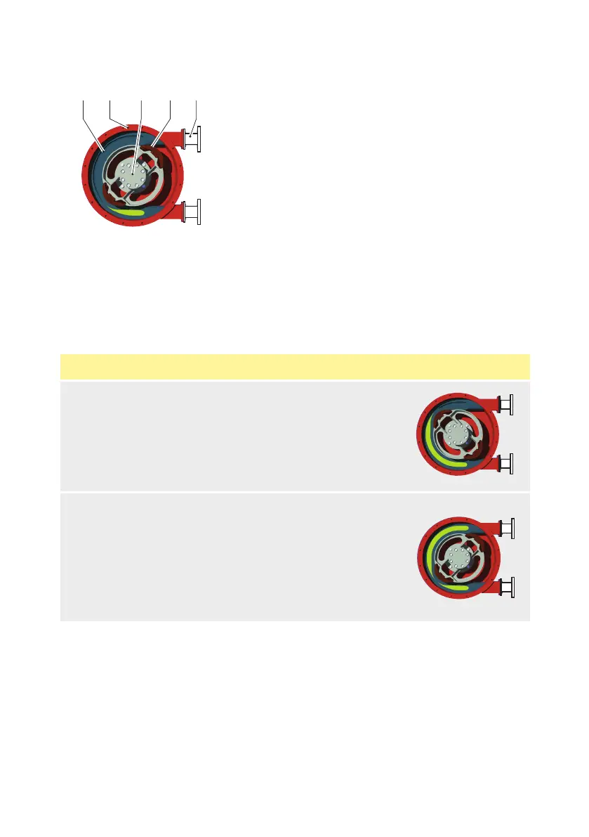
The heart of the pumphead consists of a specially constructed hose (A) which lies against the inside of
the pump housing (B).
The ends of the hose are connected to the suction and discharge lines by means of a flange
construction (C).
A bearing-mounted rotor (D) with two facing pressing shoes (E) is in the centre of the pumphead. In
this example, it rotates clockwise.
Phase Description Pump layout
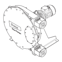
1
The lower pressing shoe compresses the hose by the
rotational movement of the rotor, forcing the fluid through
the hose. As soon as the pressing shoe has passed, the hose
recovers to its original shape sucking in new fluid.
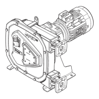
2
When the first pressing shoe leaves the pump hose, the
second pressing shoe has already occluded the hose and
fluid is prevented from flowing back. This method of liquid
displacement is known as the "positive displacement
principle".
22 m-bredel-25-32-en-05