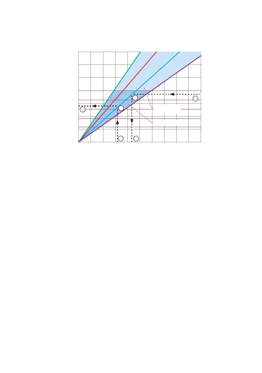
How to use the graphs
20 40 60 80 100
3500
7000 10500 14000 17500
15.4
30.8 46.2 61.6 77.1
1.0 (1.34)
0
2.0 (2.68)
3.0 (4.02)
5.0 (6.70)
4.0 (5.36)
6.0 (8.04)
7.0 (9.38)
1600 kPa (232psi)
1000 kPa (145psi)
750 kPa (109psi)
500 kPa (73psi)
40 (104)
50 (122)
60 (140)
70 (158)
80 (176)
100 kPa = 1 bar
C
D
FA
E
B
Required motor power in kW (HP)
Intermittent Duty
Continuous Duty
Product
temperature
°C(°F)
Pump speed (rpm)
Capacity (L/h)
Capacity (USGPM)
A Required flow or pump speed D Product temperature
B Required discharge pressure E Required discharge pressure
C Required motor power F Maximum allowed pump speed
Refer to the graph to understand how to use the graphs to determine the required motor power or
the maximum allowed pump speed.
To determine the required motor power:
1. Start at the required flow or pump speed (A).
2. Meet the line of the required discharge pressure (B).
3. Read the required motor power (C).
To determine the maximum allowed pump speed:
1. Start at the product temperature (D)
2. Meet the line of the required discharge pressure (E).
3. Read the maximum allowed pump speed (F).
Note: Pump stroke volume is based on new hoses and flooded suction. Actual stroke volume may
vary.
36 m-bredel-25-32-en-05