© 2022 Brivo Systems LLC. All rights reserved. PUB-Brivo ACS6100 Installation Manual
18
Brivo ACS6100 Installation Manual
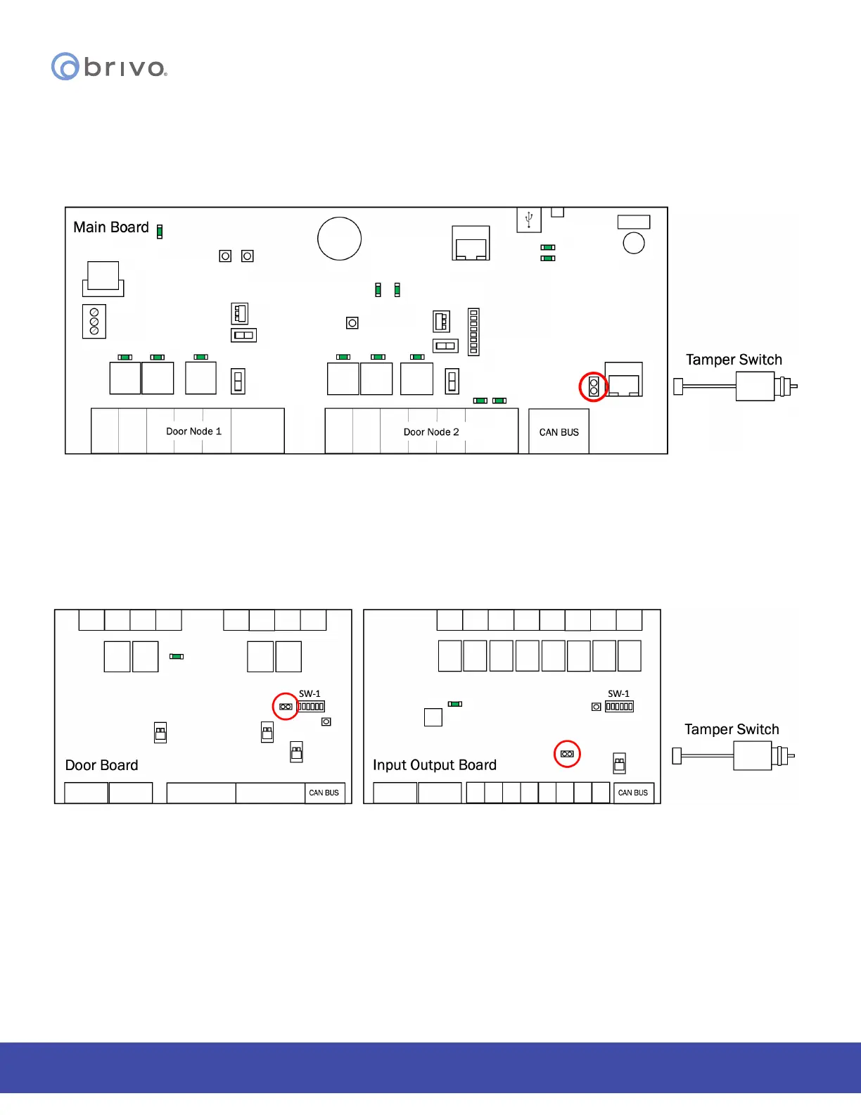
OPTIONAL: Connect the physical tamper switch to the MAIN CONTROL BOARD and to one
board in each expansion chassis.
1. Connect a user provided physical tamper switch to the MAIN CONTROL BOARD in the control chassis.
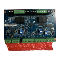
Figure 9 - Connect Tamper Switch to MAIN CONTROL BOARD
a) The tamper header connects to an optional user supplied tamper switch.
b) The header connector for the tamper switch should be connected to the TAMPER pins
located on the lower right side of the MAIN CONTROL BOARD and each expansion board.
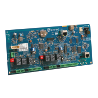
2. Connect the tamper switch to one expansion board (DOOR BOARD or INPUT OUTPUT BOARD) in each
expansion chassis.
Figure 10 - Connect Tamper Switch to Expansion Boards
NOTE: If a chassis has two or more boards, connect the tamper switch to the upper right board.
NOTE: If the tamper switch is not going to be used, leave the supplied jumper on this connector to keep the circuit
closed.