© 2022 Brivo Systems LLC. All rights reserved. PUB-Brivo ACS6100 Installation Manual
33
Brivo ACS6100 Installation Manual
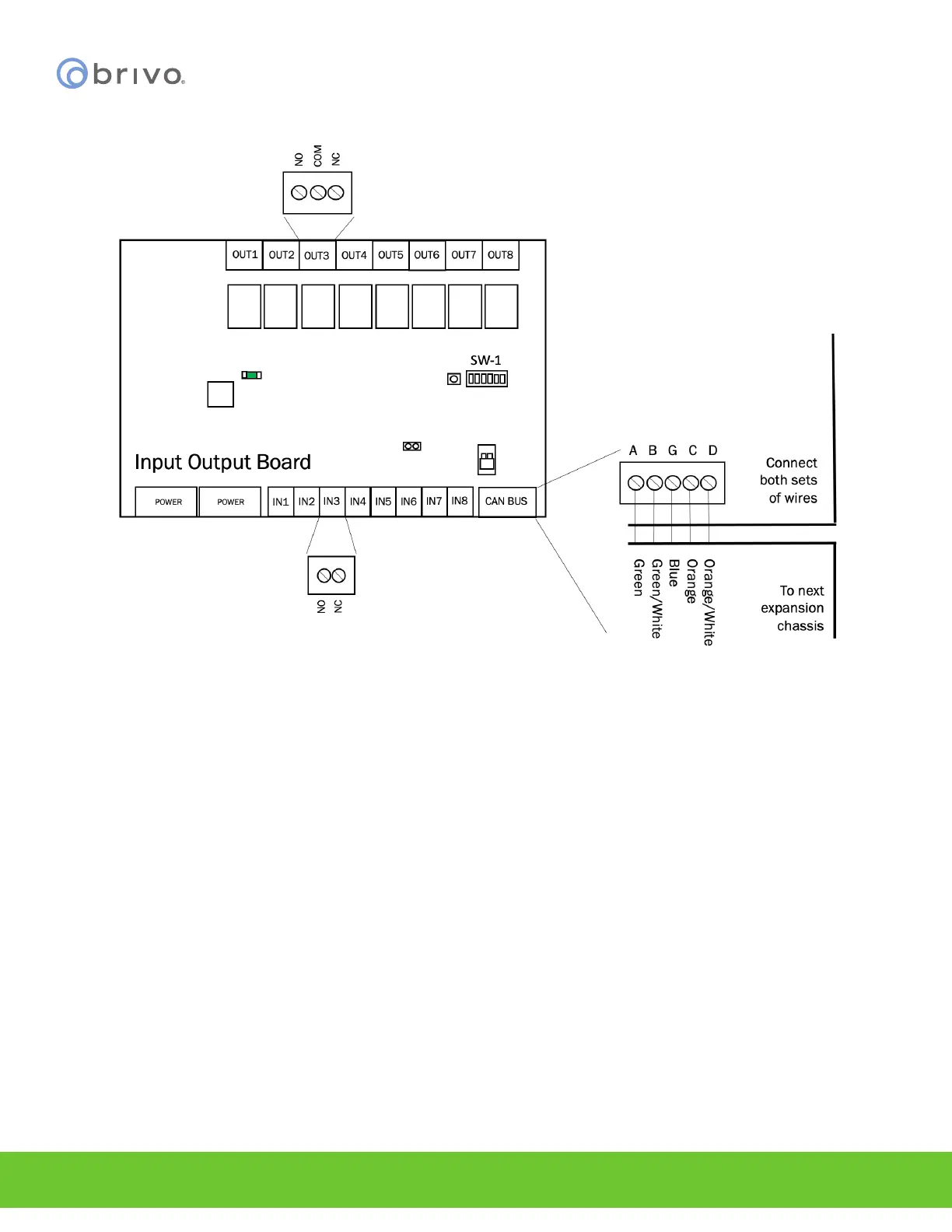
Wire INPUT OUTPUT BOARDs
Figure 26 - Wire INPUT OUTPUT BOARD
NOTE: Output Ratings for the B-ACS6100-IO Input Output Board
• Eight (8) relays on the I/O Board. The ratings are 28VDC, 3A each.
1. An INPUT OUTPUT BOARD has 8 output relays and 8 inputs. The 8 inputs are located on the bottom of the
INPUT OUTPUT BOARD and the 8 outputs are located along the top. The inputs can be wired for line
supervision.
2. The B-ACS6000-MBE/MBS control panel is capable of 4-state input monitoring at each input connector,
whether it be on the MAIN CONTROL BOARD, a Door Board, or an Input Output Board. This allows
for monitoring of not only open and closed switches, but cut and short-circuited lines as well.
This can only happen when the EOL (end-of-line) resistor wiring is installed.
a) You will need two 2K ohm resistors for each input.
b) The resistors are installed on the input lines as close to the switch as possible, and as far
from the B-ACS6000-MBE/MBS control panel.
c) One resistor is placed in parallel with the switch, so that one end of the resistor is connected
to wire 1 from the switch, while the other end is connected to wire 2 from the switch.
d) The second resistor is placed in series with the switch, so that one end of the resistor is
connected to wire 1 from the switch, while the other end is connected to the wire leading to
the B-ACS6000-MBE/MBS MAIN CONTROL BOARD.
e) The other wire from the B-ACS6000-MBE/MBS is connected to wire 2 from the switch, as
shown in Figure 21.