© 2022 Brivo Systems LLC. All rights reserved. PUB-Brivo ACS6100 Installation Manual
17
Brivo ACS6100 Installation Manual
3. If there is a standard expansion chassis, connect each DOOR BOARD and INPUT OUTPUT BOARD to the
power supply board in each chassis. If there is a large expansion chassis, connect the rst four expansion
boards (DOOR BOARDs or INPUT OUTPUT BOARDs) to the rst power supply board and the remaining
boards (up to four) to the second power supply board.
a) Use the power cable that came with each circuit board kit.
b) The power connector uses a 4-pin screw terminal block connector to deliver +12V, Ground,
Power Detection and Earth Ground to each board from the power supply.
WARNING: Power Supply
Do not use any power supply other than those supplied with your Brivo product.
WARNING: Powering Electronic Strikes and Latches
Do not power electronic strikes and latches with the battery (or other power source) used to power the control
panel. Doing so will cause damage to the Brivo control panel. Use only a UL/MET listed burglar alarm or access
control system to power electronic strikes and latches.
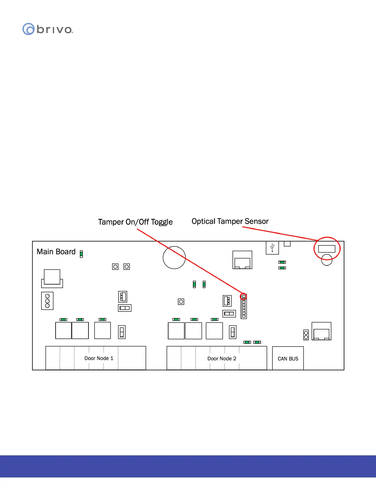
ACS6000 control panel tamper switches
The B-ACS6000-MBE/MBS control panel tamper ON/OFF toggle in the OFF position deactivates both the optical and
physical tamper switches.
Figure 8 - Tamper Switch and Optical Tamper Sensor Locations
NOTE: If the technician is installing the B-ACS6000-MBE MAIN CONTROL BOARD as a retrot in a B-ACS5000-MBE/
MBS enclosure, there is no optical reector present. The optical tamper will not function.