© 2022 Brivo Systems LLC. All rights reserved. PUB-Brivo ACS6100 Installation Manual
12
Brivo ACS6100 Installation Manual
General Assembly Procedures
Assemble and mount chassis
1. Stick the identity label to the inside of the metal chassis.
NOTE: In the top position of the chassis, standos are included to mount either a MAIN CONTROL BOARD or
two DOOR BOARDs/input-output boards. If mounting a MAIN CONTROL BOARD, clip o the four central plastic
standos.
2. Mount the chassis.
a) Use four bolts (#8 or equivalent) to mount each chassis securely in place.
b) Make sure the chassis door can swing open freely to allow for access after the installation is
complete.
c) In tight spaces, the removable hinge design of the B-ACS6100R-E/B-ACS6100L-E enclosures
allow an installer to completely remove the chassis door and replace it just as easily upon
completion of the installation.
3. Remove any knock-outs that may be required to accommodate conduit or wiring.
WARNING: Knockouts
DO NOT ATTEMPT TO REMOVE THE KNOCKOUTS WITH A HAMMER. Banging on the knockouts may result in shock
to the circuit boards, which could cause permanent damage. Pry them out using a screwdriver.
4. Assemble the chassis.
a) Install the power supply board in each chassis rst. If you install the MAIN CONTROL BOARD
or a Door or INPUT OUTPUT BOARD rst, you may nd it dicult to position your
screwdriver in a way that will allow you to install the power supply board later.
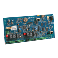
b) Install the MAIN CONTROL BOARD in the control chassis.
• Install each board by aligning it with the previously installed stand-os and then
gently pressing it into place. You will hear a slight click as the board settles into the
locked position on the standos.
• After that, screw on the ground post screw on the bottom left corner.
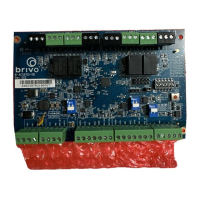
c) If there are DOOR BOARDs or INPUT OUTPUT BOARDs for the control chassis, install those
now, using the procedures described for the MAIN CONTROL BOARD.
d) If there are expansion chassis, install the appropriate DOOR BOARDs and/or INPUT OUTPUT
BOARDs in each chassis at this time, using the procedures described for the MAIN CONTROL
BOARD.
e) You will note that the control panel kit contained an adhesive Identity Label. This label
should be axed to the inside of the front door of the control chassis, beneath the large
wiring guide.
5. Verify presence of optical tamper reector on the inside of the chassis door.
6. OPTIONAL: Install a user provided physical tamper switch in the chassis.
a) Install a user provided tamper switch in the chassis by removing the hex collar, seating
the switch inside the provided mounting bracket, and reattaching and tightening the hex
collar.