98 Brocade DCX 8510-8 Backbone Hardware Reference Manual
53-1002180-03
Inter-chassis link (QSFP) cable removal and replacement
5
Possible ICL configurations
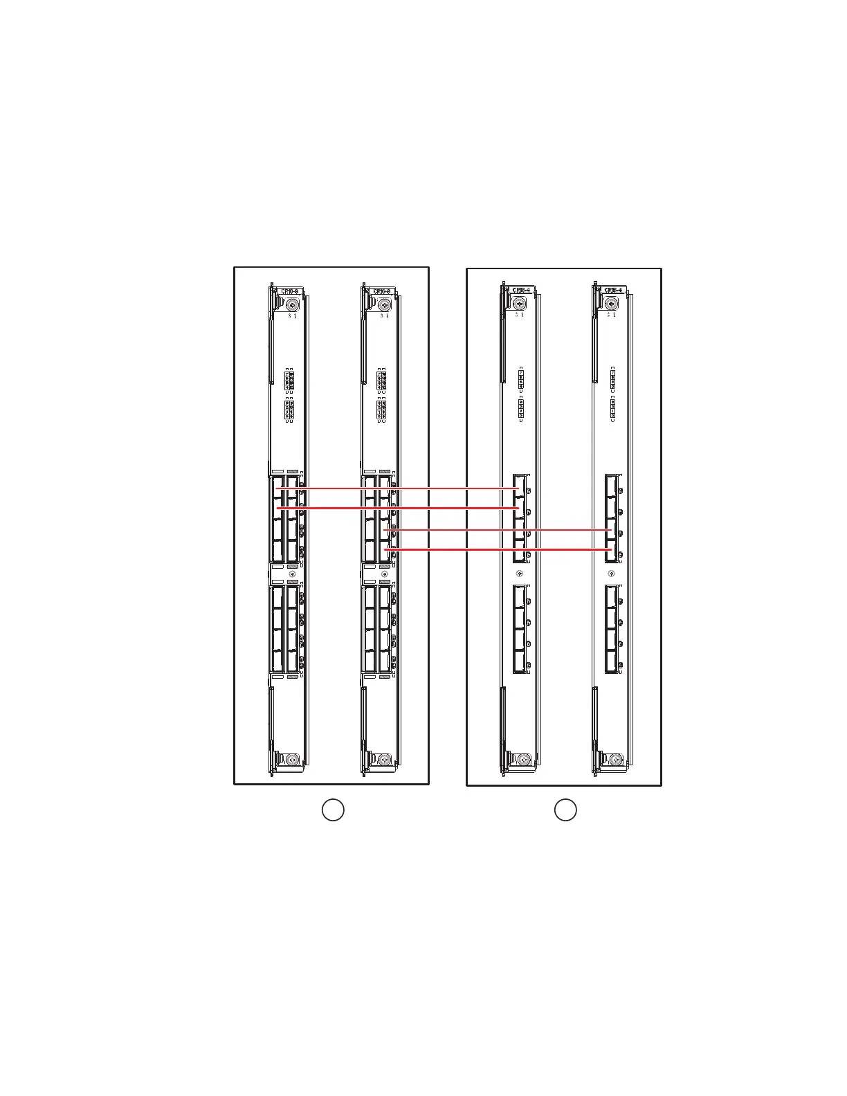
The following figure illustrates one possible QSFP cable configuration between two 8510 series
chassis. Up to six neighboring 8510 chassis can be connected as long as each of two cores in one
chassis is interconnected with each of two cores in the next chassis. This provides for inter-chassis
link (ICL) trunking between chassis, ensuring redundancy. Parallel connections between core
blades are recommended, but both parallel and mesh cable arrangements are supported.
FIGURE 32 QSFP cable connections – 8510 sample configuration - parallel type
Six 8510 chassis can be connected in a core/edge configuration (two core/four edge) as shown in
the figure below. Although 8510-8 chassis are shown in the figure, the chassis can be either
8510-4 or 8510-8. The cabling scheme should follow the parallel example shown in the previous
figure.
1 Chassis 1 2 Chassis 2

 Loading...