Brocade DCX 8510-8 Backbone Hardware Reference Manual 3
53-1002180-03
Brocade DCX 8510-8 hardware components
1
• Modular, hot-swappable field-replaceable units (FRUs):
- Three blower assemblies.
- Up to four power supplies (100-240 VAC auto-sensing).
At 110 VAC (nominal): Four power supplies are required for high availability.
220 VAC (nominal) is recommended for efficiency. Two or four power supplies are
provided depending the quantity ordered. See “Power specifications” in the
“Specifications” appendix for specific requirements for high availability.
Redundant AC primary power connections ensure high availability. Each power supply
has its own connector, so the number of primary power connections is four for
optimum efficiency and redundancy.
- Two WWN cards.
- Blades use small form-factor pluggable (SFP+, and mSFP) optical transceivers. SFP+ and
mSFP transceivers support speeds of 2, 4, 8, 10, or 16 Gbps.
The 8-Gbps SFP+s and mSFPs auto-negotiate at 2, 4, and 8 Gbps. The 16-Gbps SFP+s
auto-negotiate at 4, 8, and 16 Gbps. The 10 Gbps speeds must be manually set and
require special 10 Gbps SFP+ transceivers.
- QSFP-based inter-chassis link (ICL) cabling running at 64 Gbps (four 16 Gbps clustered in
a single quad connector and cable).
• Blades that are serviced from the port side of the Brocade DCX 8510-8. Blowers, power
supplies, and power cables that are serviced from the nonport side.
• World Wide Name (WWN) cards on the nonport side, to maintain chassis-specific information
such as WWNs, IP addresses, and summary status information of each port blade and power
supply through LEDs.
• Redesigned cable management comb and chassis door.
• Constant intake and FRU temperature monitoring.
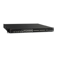
Port side of the Brocade DCX 8510-8
Airflow in the Brocade DCX 8510-8 is from the nonport (noncable) side to the port (cable) side and
out the exhaust vent.
Figure 1 displays a sample configuration of the port side of the Brocade DCX 8510-8.

 Loading...