Installing or replacing fan trays
CAUTION
For FCX624-E, FCX624-I, FCX648-E, and FCX648-I devices, be sure that the airflow direction of
the power supply unit matches that of the installed fan tray. The power supplies and fan trays
are clearly labeled with either a green arrow with an "E", or an orange arrow with an "I". On
these devices, the fan trays are hot-swappable.
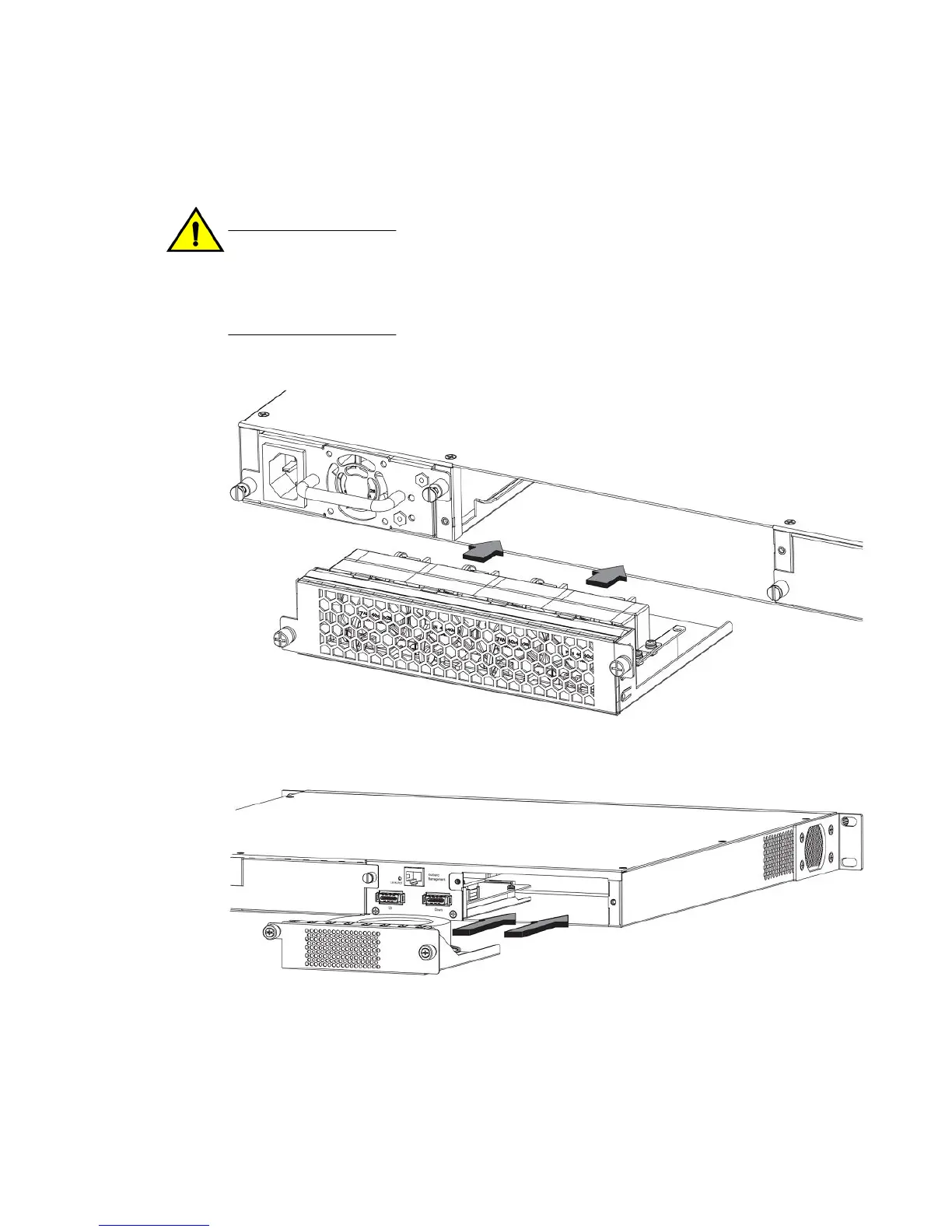
FIGURE 38 Installing a fan tray on FCX624-E, FCX624-I, FCX648-E, and FCX648-I devices
FIGURE 39 Installing a fan tray on Brocade FCX 624S, FCX 648S, FCX 624S-F, FCX 624S-HPOE,
and FCX 648S-HPOE devices
Perform the following steps to install a fan tray in the switch.
1. Remove the installed fan tray from the slot by removing the two screws with a crosshead or
Philips screwdriver.
2. Before opening the package that contains the new fan tray, touch the bag to the switch casing to
discharge any potential static electricity. It is recommended that you wear an ESD wrist strap
during installation.
Installing or replacing fan trays
52 Brocade FCX Series Hardware Installation Guide
53-1002977-01

 Loading...


