1-6
Model 0254
Section 1 Introduction
Installation and Operation Manual
X-SE-0254-eng
Part Number: 541B129AAG
September, 2010
Mounting Options
Panel Mount Kit: Brackets accept panel thickness up to 0.25 in. (6.35 mm)
Table Top Kit: Weighted base with fixed tilt for easy viewing
Rack Mount Kit: Hardware for mounting the Model 0254 and optional power
supply into 19-in. sub-rack.
Rack Mount Kit with 19-in. sub-rack: 19-in. sub-rack included with Rack
Mount Kit
Retrofit Applications, Model 0152/0154: Rack Mount Kit will adapt the
Model 0254 and power supply to the table top enclosure used for the
Model 0152/0154
Communications
Full communications capability for remote readout setpoint, control,
programming, and data acquisition
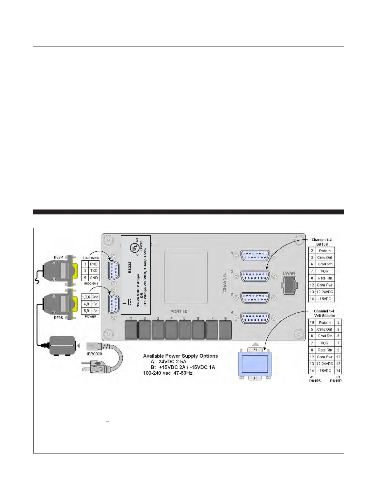
1-3 Signal Wiring
Figure 1-1 Model 0254 Signal Wiring
NOTES:
1) The following nodes are directly connected inside the 0254:
Pin 12 (COM PWR) of each DA15S channel
Pin 5 (GND) of the SERIAL PORT connector
Pins 1,2 and 6 (GND) of the +12-24 Vdc 9-Pin SUB D connector
All hex shield screwlocks for all SUB-D connectors
2) For each DA15S channel, Pins 6 (CMD RTN) and 8 (RATE RTN) are directly connected,
are connected via approximately 10KΩ to Pin 12 (COM PWR)
Pins 6 and 8 are not directly connected between channels
3) For all connectors, all unlisted pins are not internally connected