15
Installation and Operation Manual
X-DPT-Profibus-Interface-eng
PN 541-C-068-AAG
November, 2008
1 Setpoint return (-) Not used
2 0(1) - 5 Vdc Flow signal output 0(1) - 5 Vdc Flow signal output
3 (TTL) Open collector alarm output (TTL)Open collector alarm output
4 0(4) - 20 mA Flow signal output 0(4) - 20 mA Flow signal output
5 +24 Vdc Power supply +24 Power supply
6 Not used Not used
7 0(4) - 20 mA Setpoint input Not used
8 0(1) - 5 Vdc Setpoint input Not used
9 Power supply common Power supply common
10 Flow signal output common Flow signal output common
11 +5Vdc reference output Not used
12 Valve override input Not used
13 Not connected Not connected
14 RS-232 RxD/RS-485 A-
**
RS-232 RxD/RS-485 A-
**
15 RS-232 TxD/RS-485 A+
**
RS-232 TxD/RS-485 A+
**
* Not connected indicates “not electrically connected internally”. Not used indicates
“electrically connected internally, but serves no purpose”.
** Pin 14 and 15 are connected through to the piggyback board and are reserved for the
digital communication option in case the standard piggyback is installed. In case the
Profibus-DP piggyback is installed, these pins are not connected.
The minimum requirement to operate the device on a Profibus network is the
connection of the power supply lines, pin 5 (+15 Vdc to +28Vdc) and pin 9
(power supply common). For Profibus usage only +24V power supply option
is used (refer to the Installation and Operating Manual Smart TMF series,
doc. #541-C-051 and #541-C-061 for MF version).
The analogue output signals, representing a measure for the flow on pin 2
(voltage output), pin 4 (current output) and pin 10 (flow signal output common)
can be used in parallel with the network. Information on the flow can be
obtained through the network (in engineering units), but at the same time as a
voltage or current level through pin 2, 4 and 10. However, these pins can also
be set to OFF through the network, forcing them to the 0 volt/current level.
The setpoint command (Smart Mass Flow Controller models only), can be
issued either through the Profibus network or through an analogue signal
level. The user has to define the setpoint source and (in the case of an
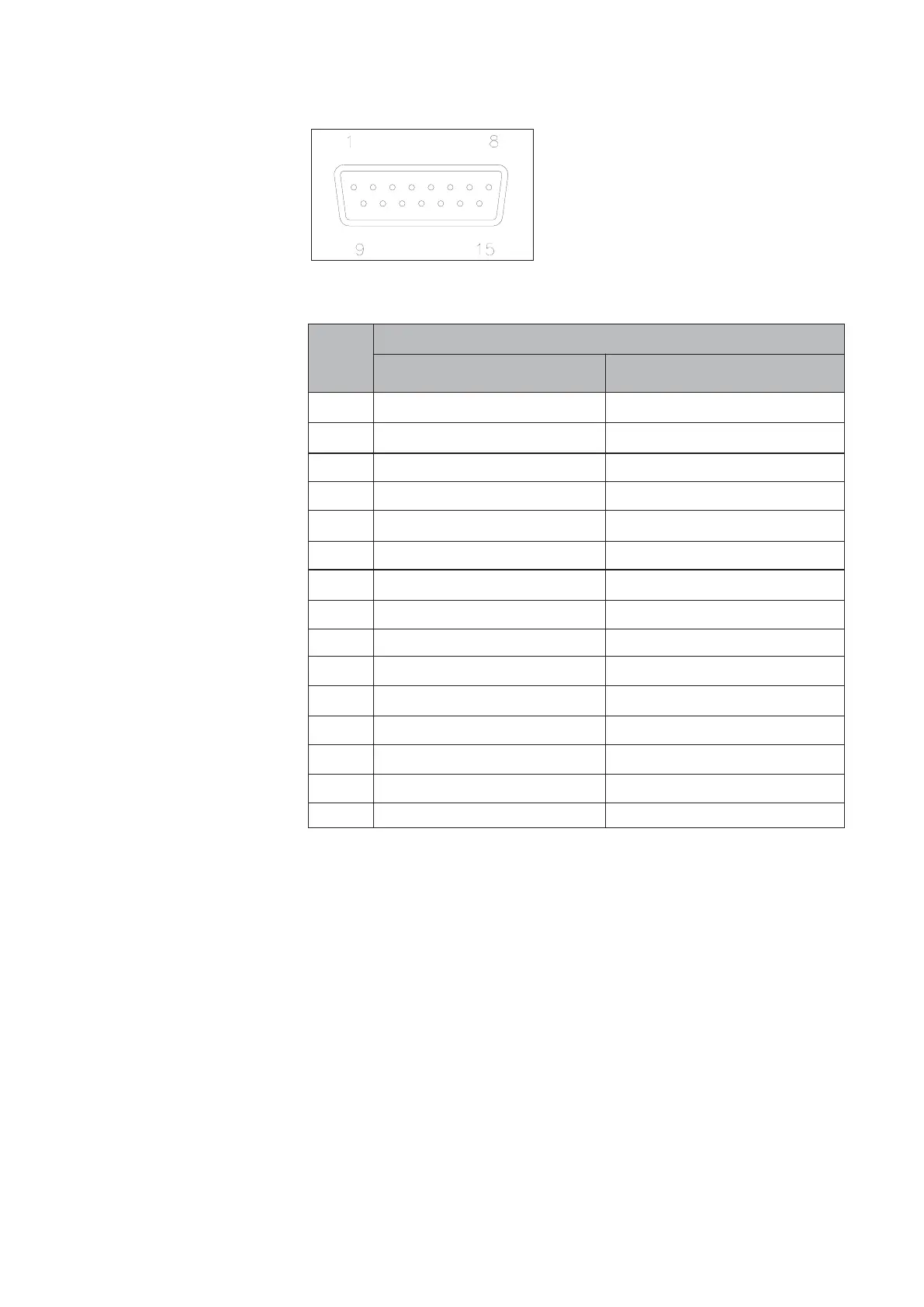
Pin
number Models
5860S, 5861S, 5863S and 5864S
Models
5850S, 5851S, and 5853S
Function
Figure 3-1: Smart TMF main 15-pin male sub-D connector - pin numbering.
Table 3-1: Smart TMF main connector pin layout.