17
Installation and Operation Manual
X-DPT-Profibus-Interface-eng
PN 541-C-068-AAG
November, 2008
The connector provides the four mandatory signals as defined in EN 50170, i.e.
RxD/TxD-P, RxD/TxD-N, VP and DGND. The other defined signals, the 24 Vdc
power supply option as well as the optional repeater control signals, are not
supported and therefore not connected on the Smart TMF series Profibus
piggyback board. The Profibus signals are galvanic isolated from the main
electronics.
The required line termination is not provided within the Smart TMF series device
itself. Refer to section 3.4 for network wiring instructions.
3.2.4 Main connector (MF series)
The MF series have a PG11 connector at the inlet side of the mass flow device
for the power supply and analogue I/O. In case of profibus no analogue I/O is
possible, except for the Valve OverRide (VOR) input. In these cases this PG11
connector is solely used for the power supply connection and the VOR input
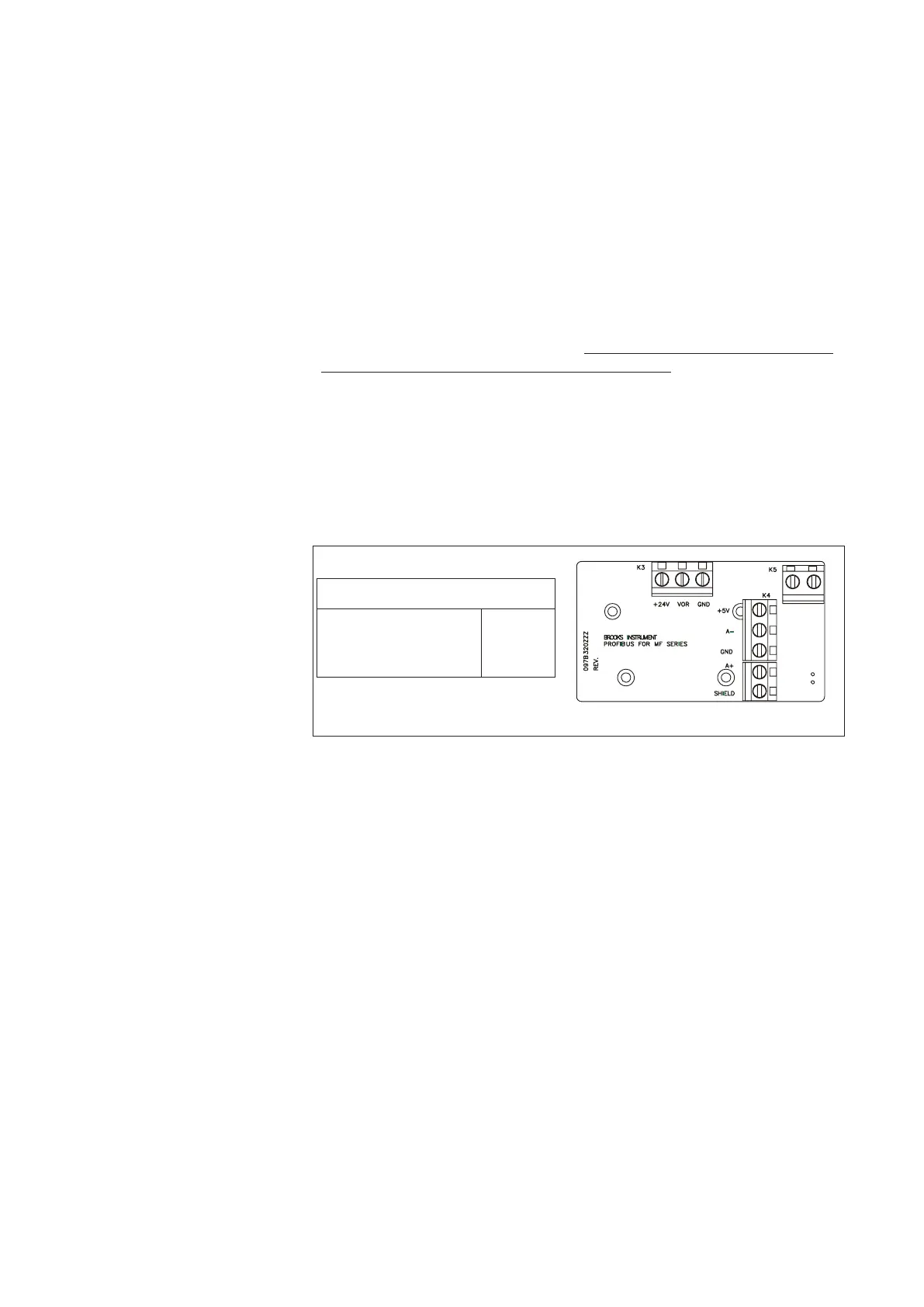
signal. Figure 3-3 shows the terminal connection location for power supply and
V.O.R. the power connection (as well as the profibus connection terminals) can
be accesseal by opening the top cover plate by removing the four polts on the
top of the cover plate.
The minimum requirement to operate the device on a Profibus network is the
connection of the power supply lines, labeled +24V and GND.
Figure 3-3: MF Profibus Main Power Connection
Main power connection (K3)
+24 Vdc +24V
VOR (Valve Override) VOR
Power supply common GND
The valve override signal, middle screw terminal labeled VOR, can always be
used in parallel to the network. The command (OPEN,or CLOSE) issued
through this VOR terminal always takes precedence over the network valve
override command. If the level on this terminal is left floating (not connected) a
valve override command issued through the network will be carried out.
NOTE: With regard to the power supply connections, the attached cable must
be as short as possible to ensure that the minimum required voltage and
current is available at the mass flow device.
Cable Shielding Earth
Cable requirements
Complaince with EMC directive 89/336/EEC, requires that the equipment be
fitted with fully screened cables with at least 80% shielding. The cables with at
least 80% shielding. The cable shielding should be connected to the PG
connector’s metal shell, and have 360 shielding at both ends. The shielding
should be connected to an earth terminal.
For translations of this instruction, see Appendix D of the MF series Instruction
and Operation manual p.n. #541-C-061-AAG: Translations of installation
instructions.