16
Installation and Operation Manual
X-DPT-Profibus-DP-Interface-eng
PN 541-C-068-AAG
November, 2008
analogue signal input) the setpoint level through the network. If the setpoint
command is to be issued through an analogue level on pin 7 (current input) or
pin 8 (voltage input) and pin 1 (setpoint return signal), it can be monitored over
the Profibus network at the same time. If the setpoint command is issued over
the Profibus network, any analogue setpoint signal on pin 7 or 8 is ignored.
The valve override input signal on pin 12 (Smart Mass Flow Controller models
only) can always be used in parallel to the network. The command issued
through pin 12 (OPEN or CLOSE) always takes precedence over the network
valve override command. If the level on pin 12 is left floating (not connected) a
valve override command issued through the network connection will be carried
out.
The TTL open collector alarm output (pin 3) can always be used in parallel with
the network. Any (enabled) system diagnostics signalling will activate the alarm
output and simultaneously result in a diagnostics message through the net-
work.
3.2.3 Additional Profibus connector (5800 series)
The Profibus-DP piggyback board is equipped with a separate female 9-pin sub-
D connector. The connector type as well as the pin layout is compatible with
the preferred connector as stated in the Profibus standard EN 50170. This
allows for the use of standard available, Profibus approved network connectors,
enabling fast and easy connection to a Profibus network. Table 3-2 below shows
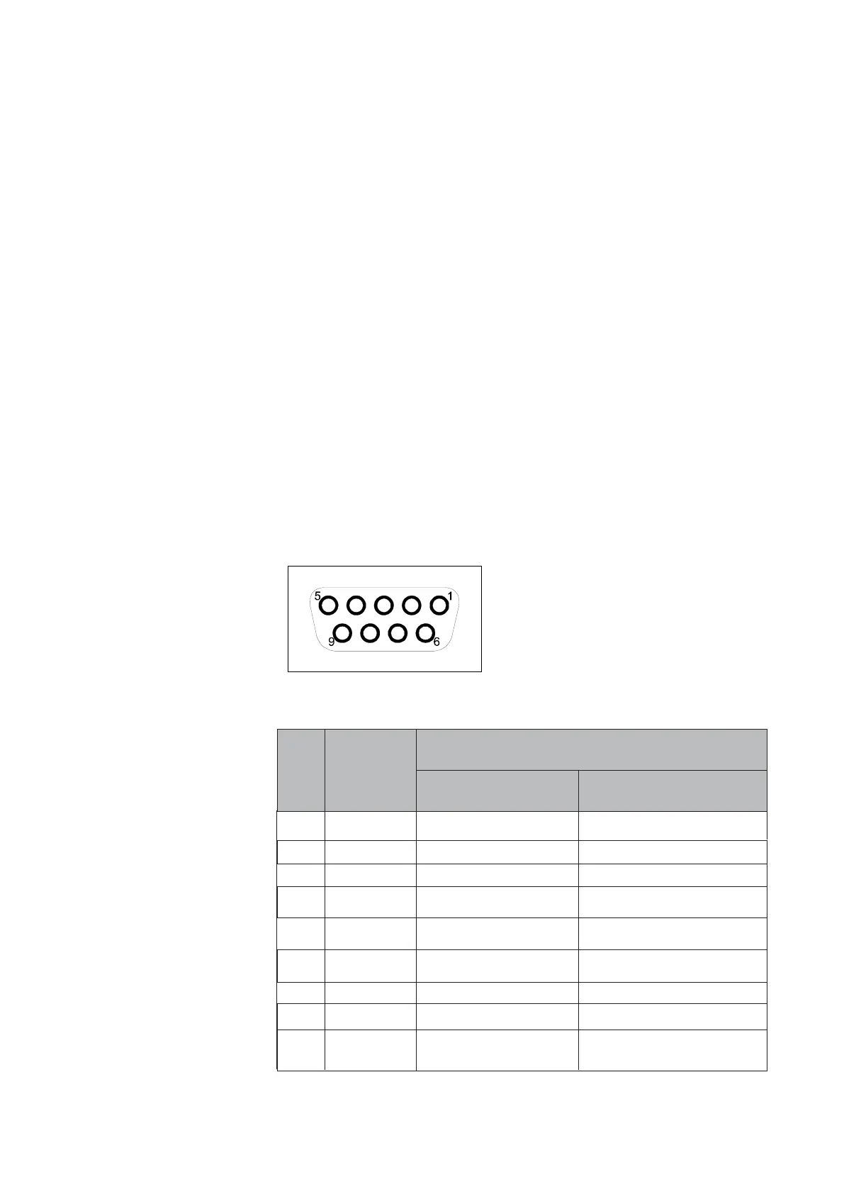
the pin numbering on the female 9-pin sub-D Profibus connector. The connector
is located on top of the Smart Mass Flow device.
Figure 3-2: Profibus 9-pin female sub-D connector - pin numbering.
Signals in bold type face are mandatory according to EN 50170.
Signal names are according to EN 50170.
Function
Pin Signal
nr.
1 Shield Connected to housing Shield/protective ground
2 M24 Not connected Ground of 24 Vdc powersupply
3 RxD/TxD-P RxD/TxD - A+ RxD/TxD - A+
4 CNTR-P Not connected Control signal for repeaters
(direction control)
5 DGND Digital ground for Digital ground for
terminating resistance terminating resistance
6 VP Digital +5 Vdc supply for Digital +5 Vdc supply for
terminating resistance terminating resistance
7 P24 Not connected 24 Vdc power supply
8 RxD/TxD-N RxD/TxD - A- RxD/TxD - A-
9 CNTR-N Not connected Control signal for repeaters
(direction control)
Smart TMF series Profibus-
DP connector
EN 50170 standard definition
Table 3-2: Smart TMF Profibus-DP network connector pin layout