2-3
Brooks
®
Digital MFC's & MFM's
Section 2 Installation
Installation and Operation Manual
X-TMF-SLA5800-MFC-eng
Part Number: 541B027AAG
April, 2013
2-8 In-Line Filter
Unless an integrated (internal) filter is already installed, it is recommended
that an in-line filter be installed upstream from the mass flow controller or
meter to prevent the possibility of any foreign material entering the flow
sensor or control valve MFC. The filtering element should be replaced
periodically or ultrasonically cleaned.
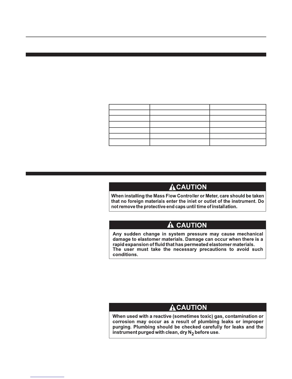
Table 2-1 Recommended Filter Size
2-9 Installation
Recommended installation procedures:
a. The Brooks Digital MFC or MFM should be located in a clean,
dry atmosphere relatively free from shock and vibration.
b. Leave sufficient room for access to Self-zero function push-button.
c. Install in such a manner that permits easy removal if the instrument
requires servicing.
d. The Brooks Digital MFC or MFM can be installed in any position.
However, mounting in orientations other than the original factory
calibration(see calibration data sheet supplied with the instrument) can
result in a<±0.2% maximum full scale shift after re-zeroing.
Models Maximum Flow Rate Recommended Filter
SLA5850/60 100 ccm 2 micron
SLA5850/60 500 ccm 2 micron
SLA5850/60 1 to 5 lpm 10 micron
SLA5850/60 10 to 100 lpm 40 micron
SLA5851/61 10 to 30 lpm 40 micron
SLA5853/63 > 100 lpm Consult factory
Note: Brooks provides many filter options. For those not listed here, please contact factory.