2-6
Brooks
®
Digital MFC's & MFM's
Section 2 Installation
Installation and Operation Manual
X-TMF-SLA5800-MFC-eng
Part Number: 541B027AAG
April, 2013
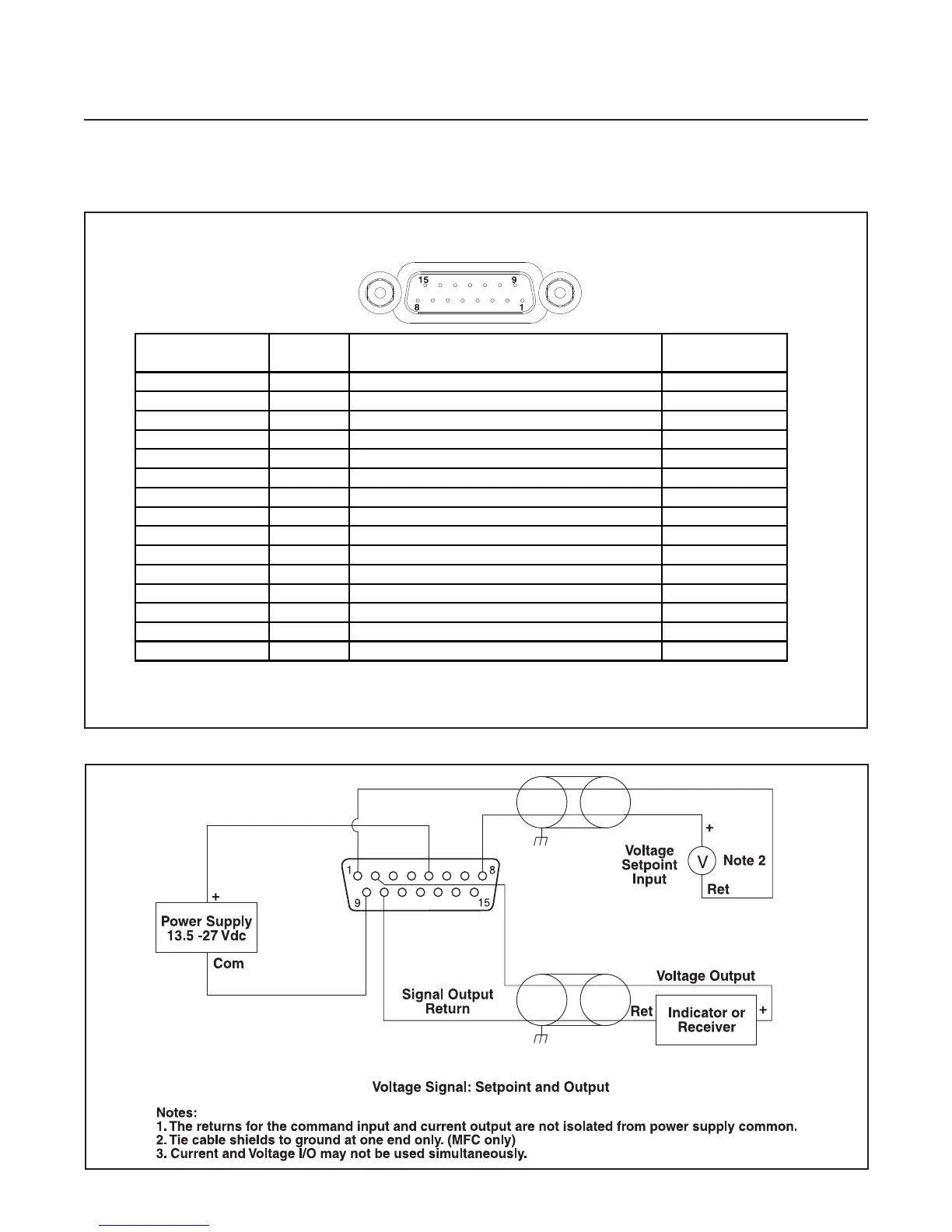
Figure 2-2 Common Electrical Hookups, Voltage I/O Version
For a DeviceNet unit, 11-25 Vdc power and communication I/O are
supplied via the standard 5-pin Circular Micro-Connector.
Figure 2-1 D-Connector Shielded Cable Hookup Diagram, Voltage I/O Version
15 PIN MALE
D-CONNECTOR
*BROOKS READ OUT MFC / MFM FUNCTION WIRE
SIDE SUB D (15 PIN) PIN COLOR
61
Setpoint, Common Input (-)
BLACK
10 2
Flow Signal
, 0(1)-5 volt, Output (+) WHITE
93
TTL Alarm, Open Collector, Output (+)
RED
24
Flow Signal
, 0(4)-20 mA, Output (+) GREEN
13 5
Power Supply, +13.5 Vdc to +27 Vdc (+)
ORANGE
14 6 Not Connected BLUE
37
Setpoint, 0(4)-20 mA, Input (+)
WHT/BLK
58
Setpoint
, 0(1)-5 volt, Input (+) RED/BLK
12 9
Power Supply, Common (-)
GRN/BLK
810
Flow Signal
, Common, Output (-) ORG/BLK
411
Reference, +5 Vdc, Output (+)
BLU/BLK
712
alve Override
, Input BLK/WHT
113
Calibration Select, Input
RED/WHT
11 14
RS-485
, Common B (-) Input/Output GRN/WHT
15 15
RS-485, Common A (+) Input/Output
BLU/WHT
* Brooks Read Out Models 0151, 0152, 0154, 0254
See Table 3-1 for Resistor values