3-85
Confidential
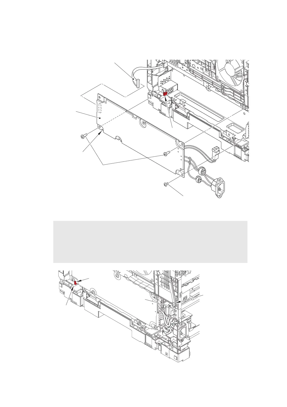
(6) Remove the screw cup M3x8 (black) screw and two taptite bind B M4x12 screws.
Remove the low-voltage power supply PCB ASSY, and disconnect the low-voltage
power supply harness from the low-voltage power supply PCB ASSY.
Fig. 3-84
Fig. 3-85
Assembling Note:
• When attaching the low-voltage power supply PCB ASSY, engage the notch on the
low-voltage power supply PCB ASSY with the hook.
• Check that the heater harness is housed in the frame L as shown in the figure below.
Otherwise the harness may be caught in some sections of the machine, and may catch
fire.
Notch
Screw cup M3×8 (black)
Taptite bind B M4x12
Low-voltage power
supply PCB ASSY
Low-voltage power supply harness
Hook
Notch
Hook
Heater harness
Heater harness is
housed in frame L
 Loading...