Do you have a question about the Brother MFC5890CN and is the answer not in the manual?
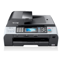
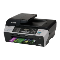
Provides an overview of the machine's external features and connections.
Describes the keys and functions of the machine's control panel.
Details the major internal components of the machine.
Covers general technical specifications and features of the models.
Details specifications related to the telephone functions of the machine.
Lists specifications and capabilities related to the FAX functions.
Lists specifications for the scanner unit.
Provides a high-level overview of the machine's architecture and components.
Details the mechanical parts and their functions, including motors and mechanisms.
Explains the electronic components and their roles in machine operation.
Explains how the machine indicates errors and lists common error messages.
Provides troubleshooting steps categorized by problem type and common issues.
Instructions for end-users on transferring received FAX data before repair.
Procedures for service personnel to back up machine information before repair.
Details procedures for disassembling and reassembling the machine components.
Crucial safety precautions to follow during disassembly and reassembly.
Specifies screw tightening torques for reassembly.
Procedure to remove the jam clear cover and inner back cover.
Lists requirements and files needed before performing adjustments.
Specific procedures for adjusting settings after replacing the head/carriage or engine unit.
Steps for updating settings after replacing the main PCB.
Instructions for cleaning the exterior and interior surfaces of the machine.
Detailed procedure for cleaning the maintenance unit components.
Steps to access the maintenance mode using the control panel keys.
A comprehensive list of available functions within the maintenance mode with reference pages.
Identifies functions accessible to end-users under service guidance.
Details the coding information for the machine's serial number label.
Explains head property labels for the head/carriage unit and ink cartridges.
Instructions for loading programs onto the machine's flash ROM.
Lists EEPROM codes for various countries and regions for customization.
Lists firmware switches and their functions, categorized by WSW number.
Provides the circuit diagram for the MJ PCB for specific regions.
Provides the circuit diagram for the 100 V series power supply PCB.
Instructions on how to delete user settings using function code 01 and power cycling.
| Print Technology | Inkjet |
|---|---|
| Max Print Resolution | 6000 x 1200 dpi |
| Max Scan Resolution | 1200 x 2400 dpi |
| Fax Modem Speed | 33.6 Kbps |
| Paper Handling | 150-sheet input tray, 50-sheet output tray |
| Monthly Duty Cycle | 3000 pages |
| Standard Memory | 32 MB |
| Supported Media Sizes | A3, A4, A5, A6, B4, B5, Executive, Legal, Letter |
| Max Print Speed (Color) | 28 ppm |
| Scanner Type | Flatbed |
| Copy Speed (Color) | 20 cpm |
| Connectivity | USB 2.0 |
| Functions | Print, Copy, Scan, Fax |
| Max Copying Resolution | 1200 x 1200 dpi |
| Media Type | Envelopes, plain paper, photo paper |
| Max Print Speed (Black) | Up to 35 ppm |
| Display | LCD |