Do you have a question about the Brother MFC6800 and is the answer not in the manual?
Explains the Class 1 laser product certification and safety standards for specific models.
Details US FDA regulations for laser products and compliance labeling requirements.
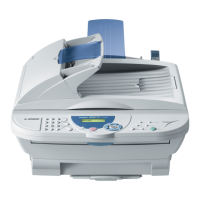
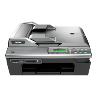
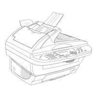
Describes the external appearance, dimensions, and approximate weight of the machine.
Lists detailed technical specifications for different models, including general, telephone, and fax features.
Provides step-by-step instructions for updating the machine's program via a PC.
Explains how to assign unique ID codes to machines after main PCB replacement.
Presents a block diagram illustrating the machine's functional sections and interconnections.
Classifies and describes the main mechanical systems: scanner, laser printing, and sensors/actuators.
Details the hardware configuration and interconnections of the machine's electronic components.
Guides service personnel through taking apart, reassembling, and lubricating the machine components.
Specifies the types of lubricants and application points for various machine components.
Lists parts that require periodic replacement, with replacement intervals.
States the Mean Time Between Failures (MTBF) and Mean Time To Repair (MTTR).
Explains the key sequences required to access the machine's maintenance mode.
Provides a table of available maintenance functions, their codes, and reference pages.
Offers in-depth explanations and operating procedures for various maintenance functions.
Details machine errors and communications errors, including LCD messages and error codes.
Outlines initial checks, precautions, and procedures for resolving common machine problems.
A list of specific codes for customizing EEPROM settings based on model and region.
Configures dial pulse generation mode, break time, and inter-digit pause.
Sets tone signal transmission time length and minimum pause in tone dialing.
Configures CNG detection and PABX dial tone detection parameters.
Sets earth function and time lengths for earth/flash functions in transfer facility.
Configures detection of the first dial tone and busy tones for dialing and call handling.
Sets pause key behavior and parameters for detecting the second dial tone.
Configures frequency band range and detection levels for dial tones.
Sets time lengths for dial tone detection and decoding error rates.
Defines frame length, retries, and timers for communication protocols.
Configures DPS switching, transmission time lengths, and encoding systems.
Sets frequency bands and ON/OFF time length ranges for busy tone detection.
Configures parameters for detecting calling signals and delays.
Adjusts modem parameters like cable equalizer, reception level, and attenuator.
Configures frequency bands and ring counts for the automatic answer mode.
Sets intervals and number of redial attempts for the redial function.
Configures CCITT superfine recommendation and document length limits.
Sets off-hook alarm behavior and calendar clock type.
Configures detection time for CNG/no tone and tone sound monitoring.
Sets initial and last transmission speeds for modem fallback in V.17 mode.
Configures settings for overseas communications, including EP tone prefix and CNG detection.
Sets erasure of stored messages and is applicable to Asian versions.
Configures ECM settings and acceptable TCF bit error rates.
Sets training check points, error rates, and decoding error rates for communications.
Sets time length for CML-ON and attenuator for ICM/OGM playback.
Configures delay time for voice signal detection and pause between paging number and PIN.
Controls dialing during document reading and CNG cycle detection.
Defines programmable key behavior and ringer OFF setting.
Sets transmission levels for DTMF high/low-band frequency signals.
Configures impedance switching and beep for activity report.
Controls duty cycle for heat-fixing unit's pulsed current.
Sets reduction rate and minimum short-OFF duration for distinctive ringing.
Configures default resolution and contrast settings.
Controls output of polled transmission requests.
Sets CNG cycle detection and DTMF tone signals for CNG inhibition.
No function specified in this entry, likely a placeholder or unused.
Configures ECP mode and PC power-off recognition time.
Controls printout of unsent document data and erasure of stored image data.
Sets equalizer, guard tone, and modem gain for V.34 mode communications.
Sets modem speed ranges for fallback in V.34 mode.
Masks symbol rates to limit transmission speed range in V.34 mode.
Configures ON-duration of fluorescent lamp and modem attenuator for V.34.
Configures incoming mail server settings and JBIG coding.
Sets wait time for PCFax reception and detection time for CED/ANSam.
Sets effective time length for white level compensation data.
Configures delay time for ADF document drawing and reference voltage correction.
Monitors PC ON/OFF state and parallel port output pins.
Circuit diagram for the main printed circuit board.
Circuit diagrams for the Network Control Unit (NCU) PCB for various regions.
Circuit diagram for the control panel printed circuit board.
Circuit diagrams for the low-voltage and high-voltage power supply PCBs.
Circuit diagram for the relay printed circuit board.
| Functionality | Print, Copy, Scan, Fax |
|---|---|
| Print Technology | Inkjet |
| Print Speed (Black) | 12 ppm |
| Print Speed (Color) | 10 ppm |
| Paper Capacity | 100 sheets |
| Operating Systems Supported | Windows, Mac OS |
| Fax Type | Super G3 |
| Fax Transmission Speed | 33.6 Kbps |
| Scan Type | Flatbed |
| ADF | Yes |
| Modem speed | 33.6 Kbps |
| Standard output capacity | 100 sheets |
| Connectivity | USB |
| Ink Cartridges | Black, Cyan, Magenta, Yellow |