Do you have a question about the Brother MFC640CW and is the answer not in the manual?
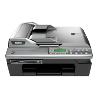
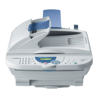
Illustrates external views, names, and functions of machine components.
Details the functions, layout, and operational keys of the machine's control panel.
Lists and illustrates the major internal and external components of the machine.
Provides general specifications including memory, ADF, paper tray, print method, and operating environment.
Details recommended paper types, sizes, and usage for different operations.
Lists detailed specifications for different models across various regions.
Presents a block diagram of the machine's sections and interconnections.
Details the various mechanical mechanisms and components within the machine.
Illustrates hardware components and their interconnections on the main PCBs.
Provides safety precautions and step-by-step procedures for disassembling machine components.
Details lubricant types and specific application points during reassembly.
Lists required executables, files, spare parts, and supplies for adjustments and updates.
Outlines procedures for updating head property info and settings after replacement.
Details steps for loading update programs, initializing EEPROM, and customizing settings after PCB replacement.
Provides cleaning procedures for maintenance unit components, including head caps and wiper.
Explains how to access the machine's maintenance mode using control panel keys.
A comprehensive list of available maintenance functions with codes and reference pages.
Provides detailed explanations and operating procedures for various maintenance functions.
Lists error messages displayed on the LCD and their probable causes.
Offers troubleshooting procedures for common problems and checks to perform before diagnosis.
Explains the serial number label format and location on the machine itself.
Details the format and location of the property label for the head/carriage unit.
Shows the serial number label format and location for individual ink cartridges.
Provides instructions on updating firmware on the main PCB from a host PC.
Explains how to set customizing codes for language and other preferences stored in EEPROM.
Configures dial pulse generation mode, break time, and inter-digit pause settings.
Sets tone signal transmission time length and minimum pause in tone dialing.
Configures CNG detection and dial tone detection for PABX environments.
Shows the wiring diagrams for the MJ PCB (various models).
Illustrates the circuit diagrams for the power supply PCB (various models).
Details the circuit diagrams for the MJ PCB across different regions.
Shows the circuit diagrams for the power supply PCB across different regions.
Explains how to view installation events logged in the event log file.
| Standard Memory | 32 MB |
|---|---|
| AirPrint Enabled | No |
| Functions | Copier, printer, scanner, fax |
| Printing Technology | Inkjet |
| Print Resolution | Up to 6000 x 1200 dpi |
| Scanner Type | Flatbed |
| Connectivity | Wi-Fi |
| Display | LCD |
| Connectivity Technology | USB, Ethernet, Wi-Fi |
| Interface | USB, 802.11b, 802.11g |