MAINTENANCE PROCEDURES
90°
rmo2010-001-008_a
Trace 2 lines parallel to the ground on
the test surface as follows:
LINES ON THE TEST SURFACE
Line A
642 mm (25.3 in) above
ground
Line B
732 mm (28.8 in) above
ground
3. Select low beam.
4. Beam aiming is correct when the
focus point (brightest spot) of the
headlight reflection is within the
marks.
1
2
A
B
rmo2010-001-302_b
TYPICAL HEADLIGHT REFLECTION ON TEST
SURFACE
1. Ground
2. Focus point
A. 642 mm (25.3 in)
B. 732 mm (28.8 in)
Headlights Aiming Adjustment
1. Remove both side panels. Refer to
BODY PANELS
in the
EQUIPMENT
subsection.
2. To adjust headlight beam, turn the
adjustment knob. Adjust both head-
lights evenly.
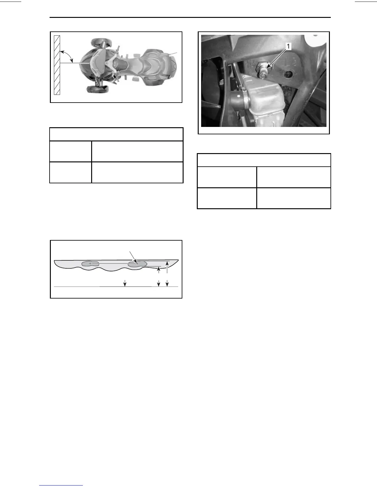
rmr2011-079-001_a
RH SIDE SHOWN
1. Adjustment knob "HB"
HEADLIGHT BEAM ADJUSTMENT
Raise beam
Turn knob
counterclockwise
Lower beam
Turn knob
counterclockwise
3. Reinstall side panels. Refer to
BODY PANELS
in the
EQUIPMENT
subsection.
______________
141