Chapter
BSMS/2 Mainframe Version 001
Bruker 11
Power Supply Modules 3
Introduction 3.1
The power requirements of the BSMS/2 are met by two modules PSB1 and PSB2 in
the back rack.The transformer is fixed on the left wall of the rack. Wiring has been
reduced to a minimum.
The mains power is switched by the mains switch, located in the line modul. With
the mains selector it is possible to set primary inputs of transformator on 195-
215VAC, 210-230VAC, or 220-245VAC. (see Primary Voltage Selection Switch on
page 14).
PSB1 and PSB2 are supplied directly from the secondary side of the transformator
which generates 20 galvanically isulated voltages. PSB1 and PSB2 provide their DC
outputs via J18 and J19 directly to the backplane.
Grounding:
The power supply is constructed so that the different BSMS/2 function elements
(SCB, SLCB, LCB,…) have individual, electrically separate power sources. These
have to be connected at designated positions (see Overview of the Power Supplies
(Part One) on page 12), thus allowing the different grounds to be joined together.
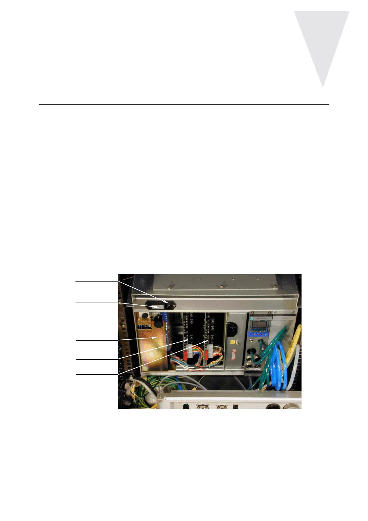
Figure 4: Power Supply Modules in the BSMS/2 (Back View)
PSB1
PSB2
Transformator
Mains Input
Fuses 2 x 5AT