BSMS/2 Mainframe Version 001
Bruker 21
Technical Data 3.6
Regulated and non-regulated voltages are shown in Table 4 and Table 5, respective-
ly. The following notes are applicable to both tables.
1. Voltages were measured with a true RMS DVM. The voltage ripple was deter-
mined with an oscilloscope and so gives an approximate value.
2. The rated load was simulated by a resistor.
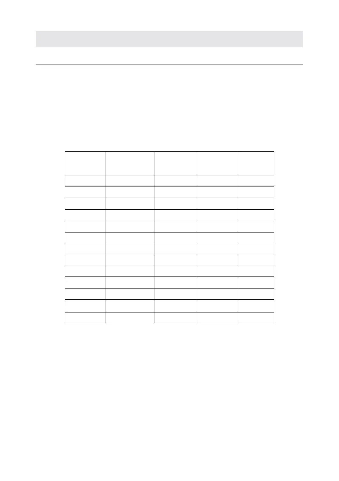
Table 4. Regulated Voltages
Vo ltage
Name
Reference
point
Voltage at
rated load
Current at
rated load
Voltage
ripple
VCC DGND 5 +/– 0.1 V 5.0 A 20 mV
VDD12 DGND 12 +/– 0.7 V 2.5 A 30 mV
VSS12 DGND –12 +/– 0.7 V 2.5 A 30 mV
H0_P H0_GND 29.5 +/– 1.8 V 0.5 A 20 mV
H0_N H0_GND –29.5 +/– 1.8 V 0.5 A 20 mV
LOCK_P15V LOCK_AGND 15 +/– 0.6 V 1.0 A 20 mV
LOCK_N15V LOCK_AGND –15 +/– 0.6 V 1.0 A 20 mV
LOCK_P5V LOCK_DGND 5 +/– 0.25 V 1.0 A 20 mV
LOCK_N5V LOCK_DGND –5 +/– 0.25 V 1.0 A 20 mV
VDD AGND 15 +/– 0.6 V 1.0 A 20 mV
VSS AGND –15 +/– 0.6 V 1.0 A 20 mV
VDD28 VDD28 27.8 +/- 1.1V 2.0 A 20mV
X5V XGND 5 +/– 0.3 V 1.0 A 20 mV
 Loading...


