Power Supply Modules
20 Bruker
BSMS/2 Mainframe Version 001
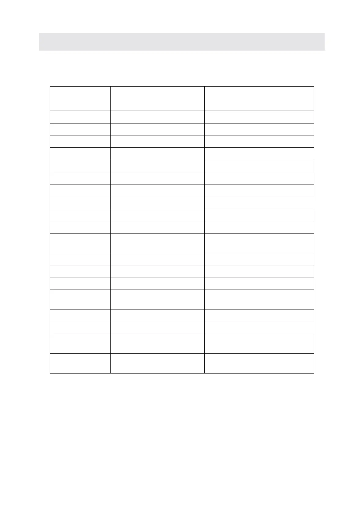
Table 3. Corresponding operation indictor LED’s
Power Supply
Board
PSB Voltage (LED) Operation Indicator (LED)
PSB1 HE_P SLCB (HE_30V)
PSB1 VDD CPU (+/-15V)
PSB1 VSS CPU (+/-15V)
PSB2 X10V & X5V CPU (X5V)
PSB1 PNEU_24V SLCB (PNEU_24V)
PSB2 VDD28 CPU (VDD24)
PSB1 VDD12 CPU (+/-12V)
PSB2 VSS12 CPU (+/-12V)
PSB2 H0_P LCB (+15V, +5V)
PSB2 H0_N LCB (–15V)
PSB2 LOCK_P15V L-RX (+/– 15V, L-PWR),
L-TX (L-PWR)
PSB2 LOCK_N15V L-RX (+/– 15V, L-PWR)
PSB2 LOCK_P5V L-TX (+/– 5V)
PSB2 LOCK_N5V L-TX (+/– 5V, L-PWR)
PSB1 VCC READY and ERROR LED’s on all
boards. If none are lit, VCC is defective.
PSB2 VPWR_N1 SCB R in SLOT 12 (VPWR_VSS)
PSB2 VPWR_P1 SCB R in SLOT 12 (VPWR_VDD)
PSB1 VPWR_P2 GAB, SCB L, M in SLOT 6, 8, 10
(VPWR_VDD)
PSB1 VPWR_N2 GAB, SCB L, M in SLOT 6, 8, 10
(VPWR_VSS)