Technical data
and startup
8.3.1 Pin 1 GND (ground terminal 31)
If DMC5x4 control signals are connected with other vehicle components, then the connection to the
vehicle's ground must take place at this pin.
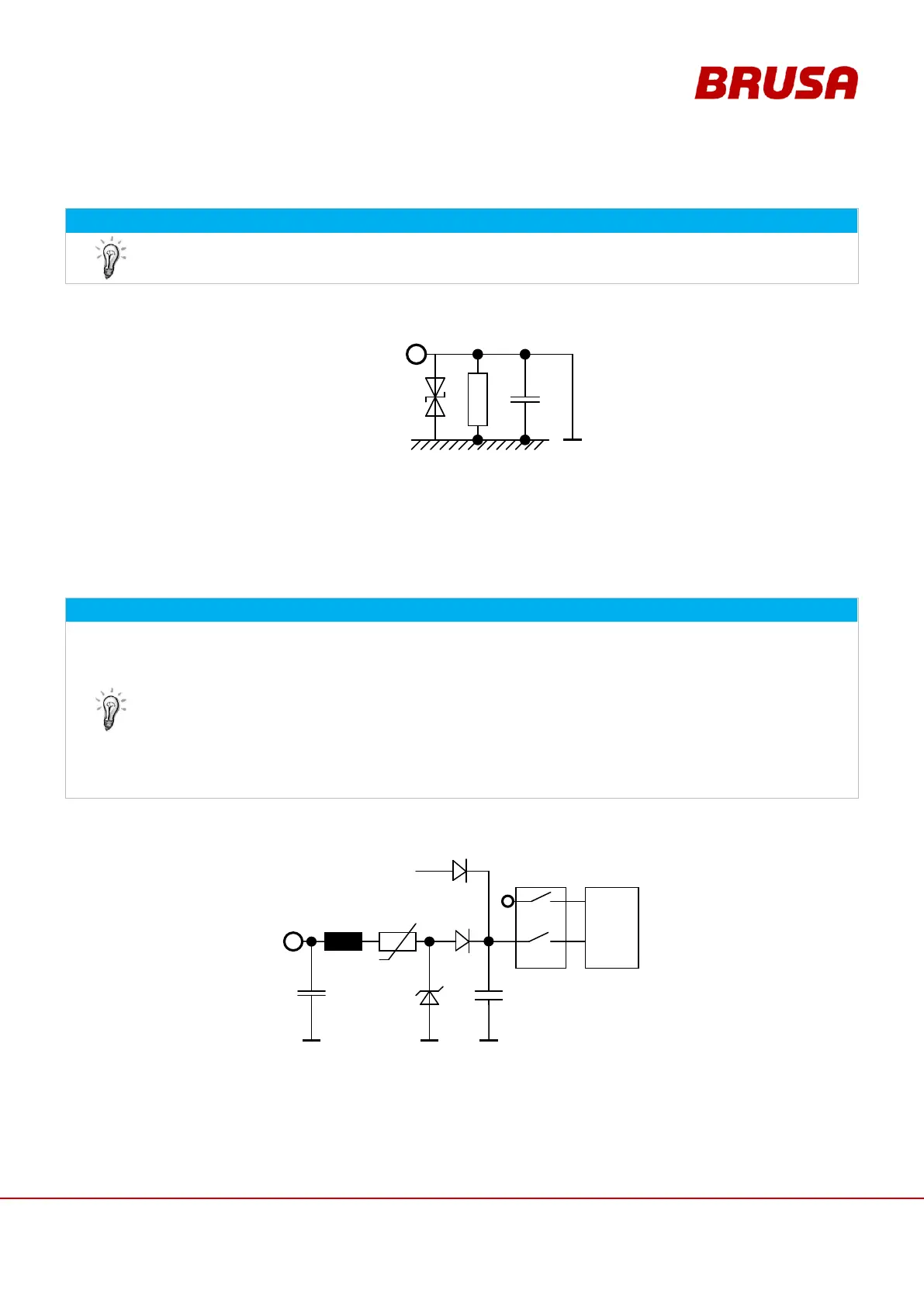
Direct ground connection of the inverter's control electronics.
The signal ground is connected with the inverter housing through a few components. These components serve for
self protection and constitute a defined connection.
8.3.2 Pin 2 AUX (Wiring system terminal 30)
Aside from the HV inputs, this 12 V inlet is also necessary for the functioning of the inverter!
The inverter is generally ready for operation when the following requirements are met:
Voltage is applied at the HV inlet (> V
DCmin
)
Voltage is applied at pin 2 (terminal 30)
Pin 17 and pin 18 are active,
see chapt. 8.3.7 Pin 17 EXT AW1, Pin 18 EXT AW2 (External shut down path 1 + 2)
Pin 1 (terminal 31) is connected
No error messages present
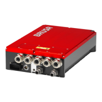
The internal 5 V supply is generated with this pin and offers the following possibilities:
CAN communication
Microprocessor programming (firmware)
Voltage measurement
As soon as HV is applied, LV is released:
If HV voltage = 0 V, LV is loaded with </= 150 mA