Technical data
and startup
If HV voltage > 100 V, the wiring system is loaded with </= 30 mA.
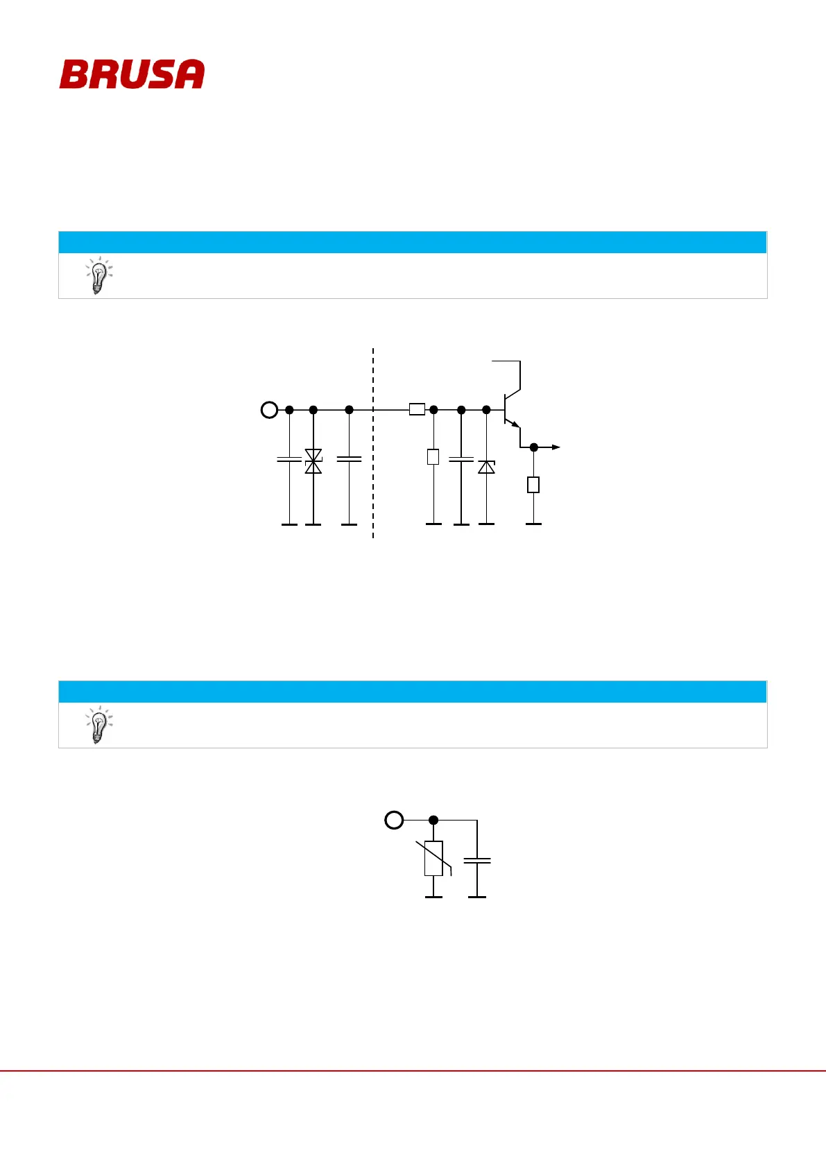
8.3.3 Pin 3 EN (Enable, Power ON)
To program new firmware, pin 3 must be high!
If voltage is applied at pin 2 and pin 3 = high, this effects the start-up of the controller. Communication with the
inverter is thereby enabled. If additional HV voltage is applied, this effects the activation of Ready mode.
The internal device logic is only fed if pin 3 = high. This is also the case if HV+ and HV- are already applied in high
voltage. Pin 3 has the function of terminal 15.
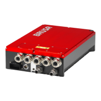
8.3.4 Pin 8 PG1, 14 PG2, 15 PG3 (Reserve ground, RS232 ground)
The additional ground connections are intended to simplify the external wiring.
Pin 8 PG1
Pin 14 PG2
Pin 15 PG3
The pins 8, 14 and 15 are each connected with pin 1 GND via a reversible fuse (PTC) and are thereby protected.
The following allocation is recommended:
Pin 8: Reserve
Pin 14: CAN-GND
Pin 15: 9 pole D-Sub: Pin 5