EasyManua.ls Logo

Brusa DMC524 - Page 57

Default Icon
65 pages
Print Icon
To Next Page IconTo Next Page
To Previous Page IconTo Previous Page
Loading...
57
Technical data
and startup
PROCEDURE STEP
ILLUSTRATION / OTHER INFORMATION
3.
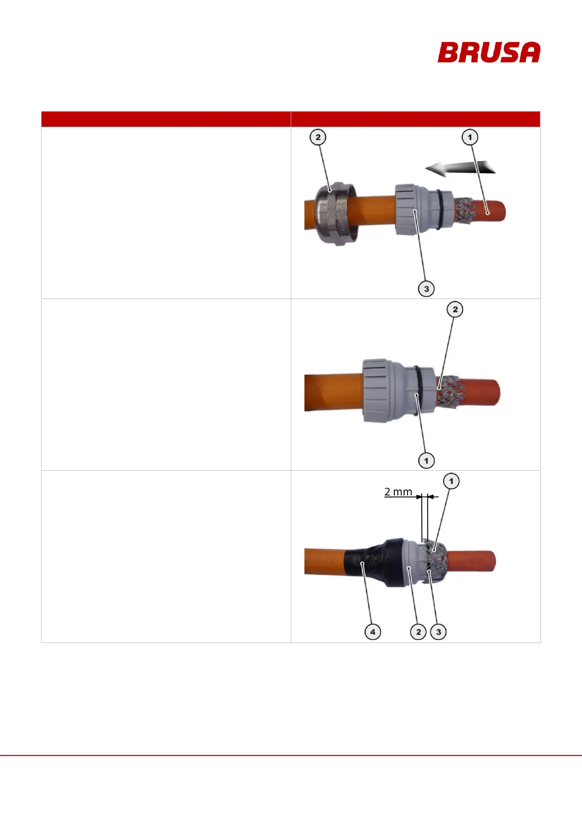
Lead the HV cable (1) through the union nut (2).
Lead the HV cable (1) through the terminal insert (3).
4.
Place the terminal insert (1) with the front edge flush
with the cable insulation (2).
5.
Put the shielding braid (1) over the terminal
insert (2).
During this, the shielding braid (1) may overlap the
O-Ring (3) by a maximum of 2 mm.
Fix the terminal insert (2) in position on the HV
cable, eg. with electrical tape (4).

Table of Contents

Related product manuals