Do you have a question about the Bryant 574D----A and is the answer not in the manual?
| Brand | Bryant |
|---|---|
| Model | 574D----A |
| Category | Air Conditioner |
| Language | English |
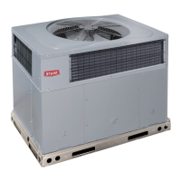
Key advantages and components of the unit, including Puron refrigerant and easy installation.
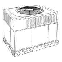
Details the unique construction of the unit base, focusing on drainage and stability.
Explains the flexibility in duct connection orientation for various installations.
Highlights energy efficiency ratings and the direct spark ignition system.
Covers compressor and burner design for longevity and reliable operation.
Details the eco-friendly refrigerant used and its environmental benefits.
Explains the benefits of the factory-assembled design for simplified installation.
Mentions quiet operation ratings ensuring a pleasant indoor and outdoor environment.
Describes the accessibility for maintenance through multiple removable panels.
Explains the initial coding for unit type (e.g., packaged gas heating/electric cooling).
Details cooling capacity and electrical supply coding for major series.
Covers heating input, brand, and optional features in the minor series.
Provides SEER, EER, and net cooling capacities for different unit sizes.
Lists heating input, output, and AFUE ratings for various models.
Presents octave band sound pressure levels (dBA) for different units.
Lists nominal cooling capacity, heating input, and shipping weights.
Details refrigerant quantity and coil dimensions (rows, fins/in., face area).
Provides data for outdoor and indoor fans/blowers (CFM, diameter, motor HP).
Lists burner orifice, pressure switch, and filter specifications.
Describes alternative coil types and compressor start kits for single-phase units.
Details economizer controls and filter rack options for vertical applications.
Lists kits for fuel conversion and duct transitions.
Covers low ambient kits for low-temperature operation and outdoor coil grilles.
Illustrates vertical and horizontal economizer setups and components.
Shows the construction and installation of the filter rack.
Depicts the installation of the manual air damper for outdoor air intake.
Provides detailed measurements for unit sizes 24-36, including weights and CG.
Shows top, front, side, and rear views with clearance requirements.
Provides detailed measurements for unit sizes 42-60, including weights and CG.
Shows top, front, side, and rear views with clearance requirements.
Details dimensions for small/common and large roof curbs for installation.
Illustrates how units are positioned on common curbs for proper fit.
Step 1: Identify design cooling conditions (TC, SHC, temp).
Step 2: Choose unit using cooling capacity tables and CFM.
Step 3: Choose unit for design heating requirement using capacity tables.
Step 4: Calculate static pressure and select fan settings.
Step 5: Match unit to available electrical supply (voltage, phase, Hz).
Cooling performance tables showing capacity, kW, and EWB for the 24-ton unit.
Explains abbreviations and provides important notes for performance data.
Cooling performance tables showing capacity, kW, and EWB for the 30-ton unit.
Cooling performance tables showing capacity, kW, and EWB for the 36-ton unit.
Cooling performance tables showing capacity, kW, and EWB for the 42-ton unit.
Cooling performance tables showing capacity, kW, and EWB for the 48-ton unit.
Cooling performance tables showing capacity, kW, and EWB for the 60-ton unit.
Defines abbreviations used in performance data tables (e.g., EWB, SHC, TC).
Provides formulas for calculating sensible capacity and enthalpy.
Explains factors affecting performance ratings like fan heat and frost.
Tables showing CFM, heating rise, and motor specs for horizontal discharge units.
Tables showing CFM, heating rise, and motor specs for horizontal discharge units.
Tables showing CFM, heating rise, and motor specs for horizontal discharge units.
Tables showing CFM, heating rise, and motor specs for horizontal discharge units.
Tables showing CFM, heating rise, and motor specs for horizontal discharge units.
Tables showing CFM, heating rise, and motor specs for horizontal discharge units.
Tables showing CFM, heating rise, and motor specs for horizontal discharge units.
Tables showing CFM, WATTS, BHP, and heating rise for downflow discharge.
Tables showing CFM, WATTS, BHP, and heating rise for downflow discharge.
Tables showing CFM, WATTS, BHP, and heating rise for downflow discharge.
Tables showing CFM, WATTS, BHP, and heating rise for downflow discharge.
Tables showing CFM, WATTS, BHP, and heating rise for downflow discharge.
Tables showing CFM, WATTS, BHP, and heating rise for downflow discharge.
Tables showing CFM, WATTS, BHP, and heating rise for downflow discharge.
Tables showing CFM, WATTS, BHP, and heating rise for downflow discharge.
Tables showing CFM, WATTS, BHP, and heating rise for downflow discharge.
Tables showing CFM, WATTS, BHP, and heating rise for downflow discharge.
Tables showing CFM, WATTS, BHP, and heating rise for downflow discharge.
Tables showing CFM, WATTS, BHP, and heating rise for downflow discharge.
Tables showing CFM, WATTS, BHP, and heating rise for downflow discharge.
Tables showing CFM, WATTS, BHP, and heating rise for downflow discharge.
Data for wet coil pressure drop at various CFM levels.
Data for economizer filter pressure drop at various CFM levels.
Orifice sizes and manifold pressures for natural gas operation at different altitudes.
Orifice sizes and manifold pressures for propane gas at different altitudes.
Heating input derating for propane gas at various altitudes above sea level.
Heating input derating for natural gas at various altitudes above sea level.
Illustrates typical rooftop installation setup with ductwork connections.
Shows typical installation for ground level units with gas and power connections.
Requirements for condensate management and duct connection methods.
Instructions for downflow conversion and airflow guidelines.
Specifies minimum ambient temperatures for cooling and heating operation.
Tables for voltage, compressor, fan, and motor data (RLA, LRA, FLA, MCA, MOCP).
Explains how to calculate and interpret voltage imbalance for 3-phase power.
Shows the electrical connections for single-phase units (208/230V).
Overview of component locations within the unit for wiring reference.
Shows electrical connections for three-phase units (208/230V).
Overview of component locations within the unit for wiring reference.
Shows electrical connections for 460V three-phase units.
Overview of component locations within the unit for wiring reference.
Describes the sequence of operations during heating mode initiation and shutdown.
Describes the sequence of operations during cooling mode initiation and shutdown.
Overview of the unit's capabilities, construction, and performance.
Lists standards and certifications the unit meets (ARI, UL, ISO).
Details cabinet construction, insulation, and fan types used.
Specifies refrigerant expansion device and control system features.
Describes available coil, compressor start, and thermostat options.
Details economizer, filter rack, and roof curb options.
Lists conversion kits, dampers, and Time Guard II features.