15
Output Connections
8.0 Output Connections
8.1 XLR Plugs
The four signal outputs are DC blocked low impedance unbalanced from a
standard 3 pin male XLR and are designed to drive up to +20dBv into 600
ohms or greater. The wiring convention is as follows:
Pin 1: Connects to shield, screen or drain wire.
Pin 2: '+', hot or 'in phase' output.
Pin 3: '-', cold or 'out of phase' output.
If the amplifiers you are feeding have unbalanced (single ended) inputs, but
are fed from standard pin to pin XLR cables (See above), simply link the cable
at the crossover end as follows:
Pin 1: Connects to shield or screen wire.
Pin 2: Link to Pin 1.
Pin 3: Connects to the inner 'hot' or live core.
Unbalanced transmission is not recommended for connections to distant
equipment, but is generally acceptable for local connections within the rack,
or to an adjacent rack.
Technicians note: As with a traditional transformer balanced output, either
output phase (+ or -, hot or cold) can be linked to ground to 'unbalance the
line' without upsetting the operation of the unit. BSS follows the convention of
'screen goes forward with the signal'. As with a transformer, output level
remains the same in the unbalanced mode.
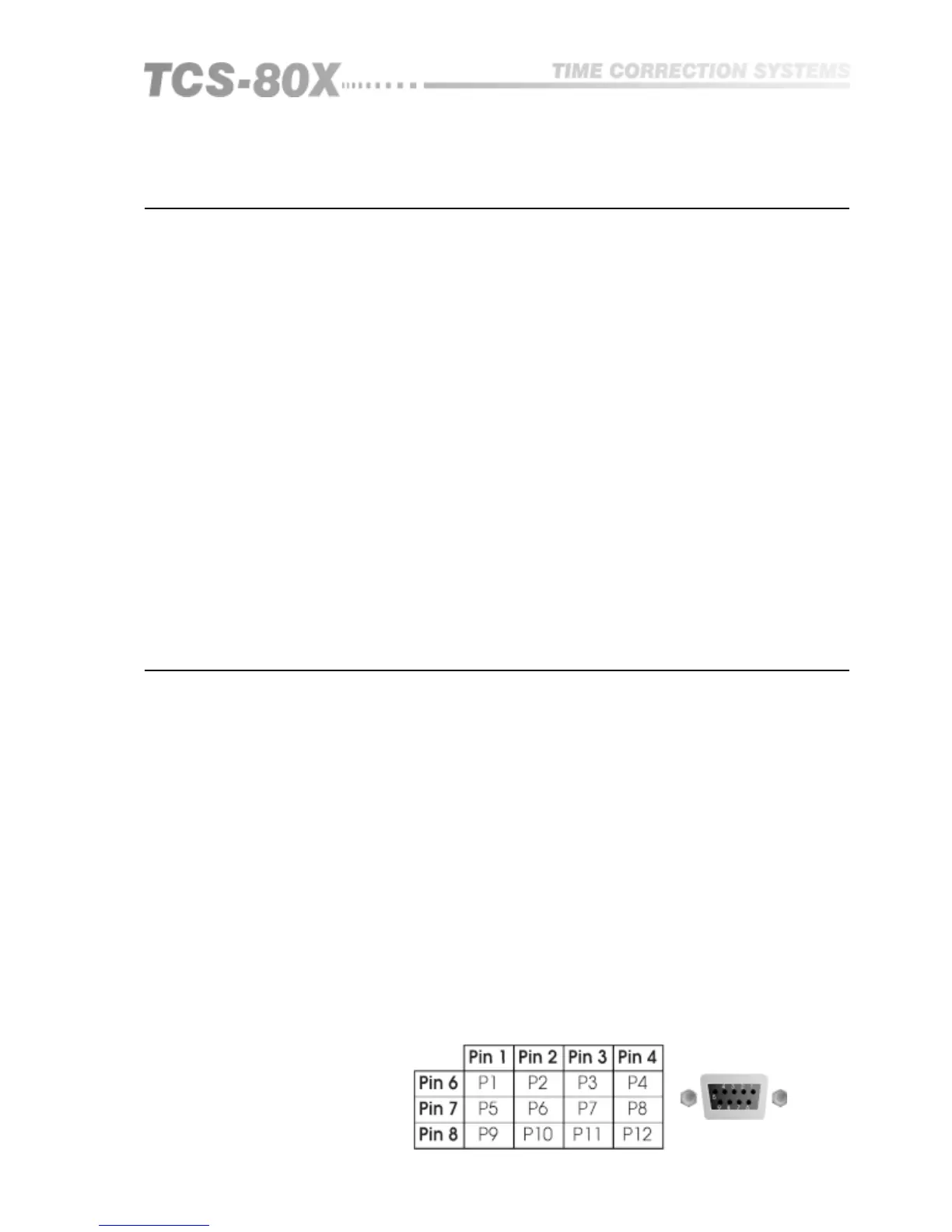
Both the TCS-803 and TCS-804 have two external control ports, one being the
Remote Program Selection, the other a standard MIDI control interface having
both IN, THRU and OUT connectors. More about the MIDI option and its
control codes are detailed in section 15. The 9 pin Remote Program Selection
'D' type connector is wired as a 4 by 3 matrix which allows by simple switch
closure, the selection of 12 user programmable memories. Figure 9.1 gives the
matrix pinning for each program number.
The voltage available at these pins is less than 5V and current limited, so that
no particular attention needs to be paid to safety and either momentary or
latching switch closure is all that is required to recall a memory number.
Individual screened cable is not required to connect your remote switching
box to the TCS-80X, however it is recommended that you use a cable that has
an overall screen, which should be connected to your control box at one end
and the designated pin on the D-Connector at the other end.
PX is the program number which is recalled by connecting together the two
designated pin numbers. Pins 5 and 9 are connected to ground
Remote Program
Selection
Fig 9.1 Remote Program
Selection D-Connector
Wiring
9.0 Control Connections
Control Connections