27
Selecting DUAL CHANNEL mode in a unit gives the possiblility to link
together the delay times on each left/right group to facilitate maintaining a
stable stereo image as the overall delay time offset is adjusted.
Note that Delay 1 and Delay 2 form the first left/right group, whilst Delay 3
and Delay 4 form the second left/right group. The following example uses the
first group numbering but it applies equally to the second group.
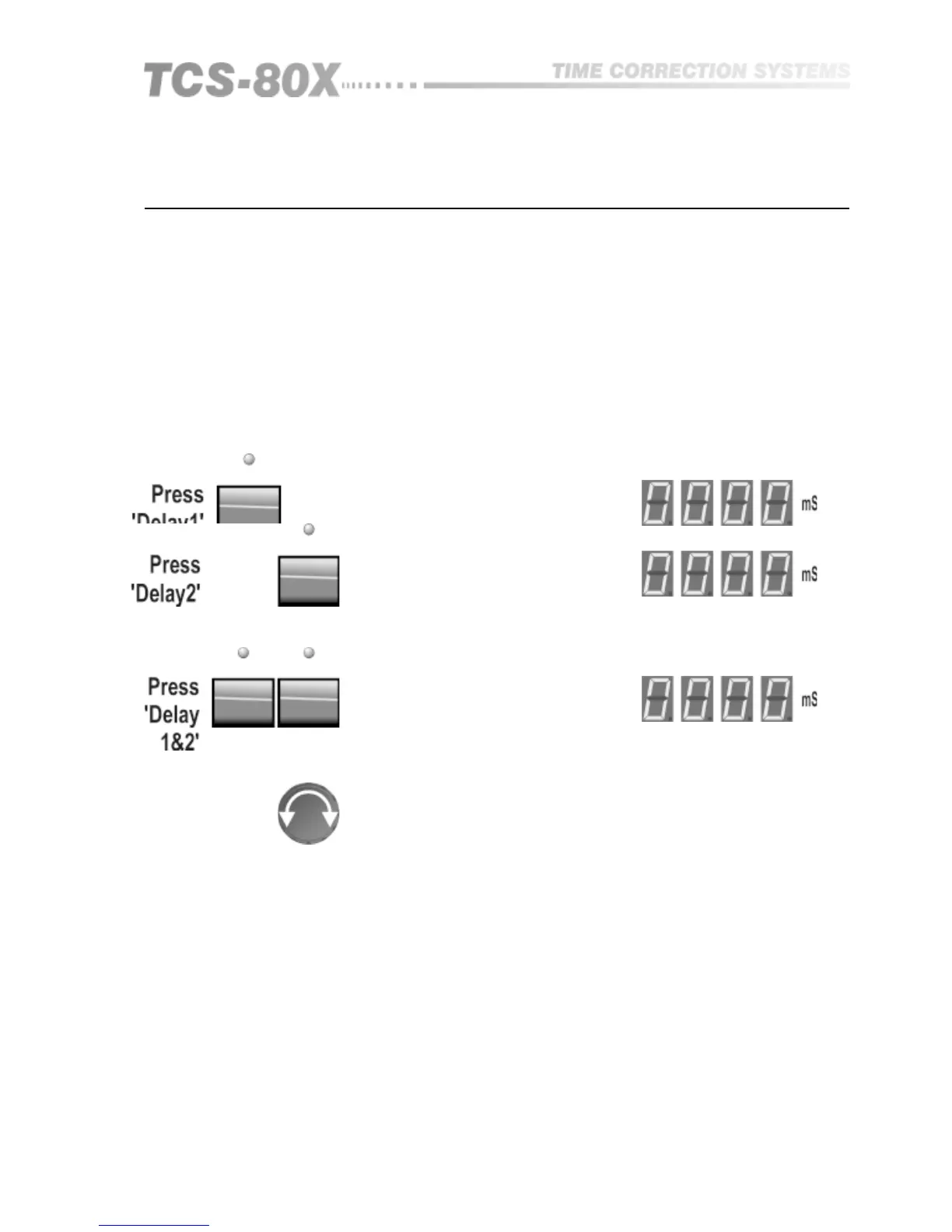
Set both delay 1 and delay 2 individually to minimum delay, or set an initial
imbalance if this is required in your particular situation.
13.0 Linking (TCS-804 Only)
13.1 Stereo Pairs
Pressing both switches SIMULTANEOUSLY cause them to become linked
together:
One of the delay indicator lights will now be flashing to show that this group
is linked, and that adjustment of one will drag the other with it.
Turn the knob to set the required delay, and the incremental change will be
applied EQUALLY to both delay 1 and 2.
Selecting either delay switch will display it’s absolute value, which will
include any initial offset that was entered prior to being linked.
When the switches are pressed again simultaneously, both units will become
unlinked.
LINKS may only be switched on or off when in the normal delay mode and
not when in Relative mode.
Note that LINKING only applies to delay time. The individual through gain for
each output remains independent and is adjustable by the LEVEL mode as
described earlier.
Linking (804 Only)