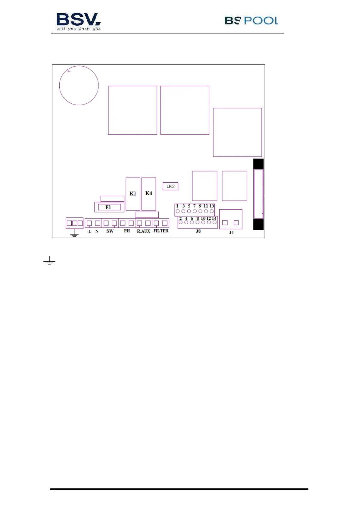
3.3- Electrical wiring diagram
3.3.1- PRO50/70 units
Earth connection
L, N: Supply 220v
SW: On / Off Switch
PH pH pump connection (For units with the AUTO kit)
AUX R: Auxiliary relay
FILTER: Filter connection for Stop / Start mode
J4: Terminal block of cell
J8:
1- (yellow) Acid sensor (PH) 8-(blue) Temperature probe
2- (yellow) Acid sensor (PH) 9-(brown) ORP-
3- (purple) Cover 10-(orange) ORP+
4- (purple) Cover 11-(red)
5- (white) Water sensor (cell’s white cable) 12-(gray)
6- (white) External flow switch (5-6)* 13-(green)
7- (blue) Temperature probe 14-(red)
* activate the FLOW SWITCH operation in the configuration menu
K1: PH Relay
K4: Auxiliary relay
LK2: Stop/Start (see 3.3.3.1)
F1: Fuse