7-60 2003 Buell XB9S: Electrical
HOME
HORN 7.21
GENERAL
The horn is located behind windscreen.
REMOVAL
1. Remove seat. See 2.41 SEAT.
1WARNING1WARNING
To protect against shock and accidental start-up of vehi-
cle, disconnect the negative battery cable before pro-
ceeding. Inadequate safety precautions could result in
death or serious injury.
2. Disconnect negative battery cable.
3. Remove headlight support bracket. See 2.25 HEAD-
LIGHT ASSEMBLY AND SUPPORT BRACKET.
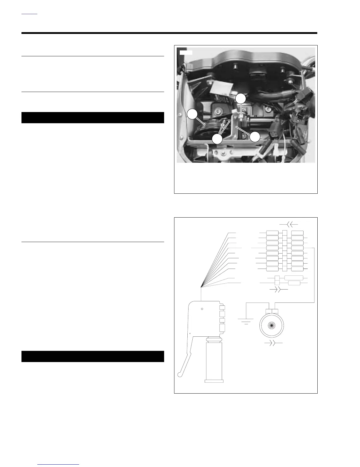
4. See Figure 7-70. Remove fastener (3).
5. Remove horn (1) from fairing support bracket (4).
6. See Figure 7-71. Detach Y/BK power wire and BK
ground wire from terminal clips on horn.
INSTALLATION
1. See Figure 7-71. Connect Y/BK power wire and BK
ground wire to terminal clips on horn.
2. See Figure 7-70. Attach horn (1) to fairing support
bracket (4) using fastener (3). Tighten to 72-96 in-lbs
(8.1-10.8 Nm).
3. Check horn operation. If horn does not sound or fails to
function satisfactorily, see TROUBLESHOOTING.
a. Turn ignition key switch ON.
b. Press horn switch to activate horn.
c. Turn ignition key switch OFF.
4. Install negative battery cable.
1WARNING1WARNING
After installing seat, pull upward on front of seat to be
sure it is locked in position. If seat is loose, it could shift
during vehicle operation and startle the rider, causing
loss of control which could result in death or serious
injury.
5. Install seat. See 2.41 SEAT.
Figure 7-70. Horn Assembly
Figure 7-71. Horn Wiring
1. Horn
2. Horn connectors [122]
3. Horn fastener
4. Support bracket
8900a
1
3
4
2
2
8
7
6
5
4
3
1
2
1
21
b1105x7x
Left Handlebar Switch
Horn
Clutch Switch
Left Handlebar Switch
Y/BK
To low beam
BE/W
Y/BK
V/BN
Light power
High beam
Horn
From flasher
Left turn
Right turn
Horn power
To interlock circuit
To ground
Y
W
Y
V
O
V
O
BN
BN
BE BE
BK
TN/LTGN
W
[24A]
[24B]
[122A] [122B]
[95A] [95B]








 To Next Page