26
Installation
8.3.3 Install control unit
Beforeinstallation,checkthepositionoftheportsonthe
controlunitand,ifrequired,aligntheactuator.
Descriptionseechapter“8.3.4Rotatingtheactuator”.
→ Removecolletfrompilotairport1.
→ CheckthattheO-ringsarecorrectlypositionedinthepilotair
ports.
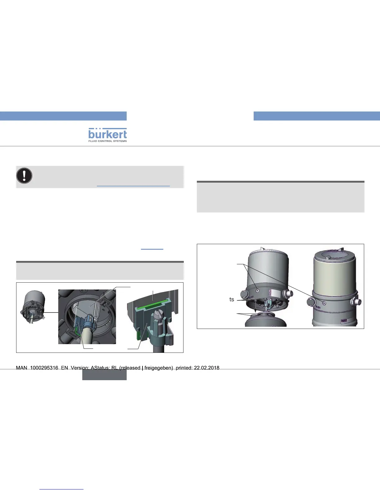
→ Alignthepuckholderandthecontrolunituntil
1.thepuckholdercanbeinsertedintotheguiderailofthe
controlunitand
2.thesupportsofthecontrolunitcanbeinsertedintothe
pilot airportsoftheactuator(seealso“Fig.21”).
NOTE!
Damaged printed circuit board or malfunction!
▶ Ensurethatthepuckholderissituatedatontheguiderail.
Guiderail
Puckholder
Fig. 20: Aligning the puck holder
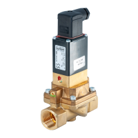
→ Pushthecontrolunit,withoutturningit,ontotheactuator
untilnogapisvisibleontheformseal.
NOTE!
Too high torque when screwing in the fastening screw does
not ensure protection class IP65 / IP67!
▶ Thefasteningscrewsmaybetightenedtoamaximum
torqueof1.5Nmonly.
→ Attachthecontrolunittotheactuatorusingthetwosidefas-
teningscrews.Indoingso,tightenthescrewsonlyhand-tight
(max.torque:1.5Nm).
Supports
Pilotairports
actuator
Fastening
screws
max.1.5Nm
Fig. 21: Install control unit