24
Installation
Type 3280, 3285
The threaded sleeve of the M12 circular connector is connected to the valve body. Connect the body to
a suitable ground connection. To ensure electromagnetic compatibility (EMC), ensure that the cable is as
short as possible and the cross-section is as large as possible.
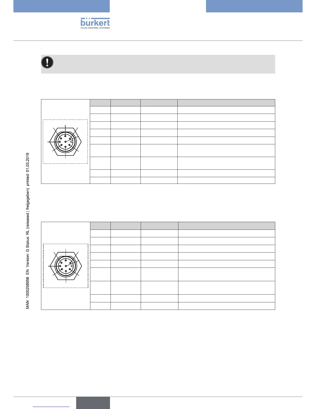
7.2.1 Pin assignment for the on-off valve, circular connector
M12, 8-pole
1
2
3
4
5
6
7
8
Pin Wire colors
*
Configuration External circuit
1
white
Supply + 24 V DC ±10 %, max. residual ripple 10 %
2
brown
Supply GND 24 V DC GND
3
green
do not connect! Electrically insulate wire on connection line
4
yellow
do not connect! Electrically insulate wire on connection line
5
grey
do not connect! Electrically insulate wire on connection line
6
rose
Digital input + 0...5 V (log. 0), 10...30 V (log. 1), not galvani-
cally isolated
7
blue
Digital output 0...5 V (log. 0), 10...30 V (log. 1), not galvani-
cally isolated
8
red
Signal GND Signal GND
Body Shielding -
*
The indicated wire colors refer to the connection cable, order no. 919061, available as an accessory.
7.2.2 Pin assignment for the control valve, circular connector
M12, 8-pole
1
2
3
4
5
6
7
8
Pin Wire colors
*
Configuration External circuit
1 white Supply + 24 V DC ±10 %, max. residual ripple 10 %
2 brown Supply GND 24 V DC GND
3 green do not connect! Electrically insulate wire on connection line
4 yellow do not connect! Electrically insulate wire on connection line
5 grey do not connect! Electrically insulate wire on connection line
6 rose Set-point value
input +
4...20 mA / 0...10 V, not galvanically isolated
PWM-signal (800 Hz)
7 blue Digital output 0...5 V (log. 0), 10...30 V (log. 1), not gal-
vanically isolated
8 red Signal GND Signal GND
Body Shielding -
*
The indicated wire colors refer to the connection cable, order no. 919061, available as an accessory.