26
Installation
Type 3280, 3285
7.2.4 Pin assignment for process controller
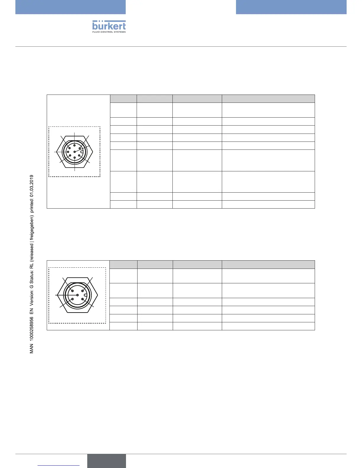
7.2.4.1 Analog version, circular connector M12, 8-pole
1
2
3
4
5
6
7
8
Pin Wire colors* Configuration External circuit
1 white Supply + 24 V DC ±10 %, max. residual ripple
10 %
2 brown Supply GND 24 V DC GND
3 green CAN low CAN low
**
4 yellow CAN high CAN high
**
5 grey CAN GND CAN GND
**
6 rose Set-point value
input +
0...20 mA / 4...20 mA / 0...5 V /
0...10 V,
not galvanically isolated
7 blue Actual value output 0...20 mA / 4...20 mA / 0...5 V /
0...10 V,
not galvanically isolated
8 red Signal GND Signal GND
Body Shielding -
* The indicated wire colors refer to the connection cable, order no. 919061, available as an accessory.
** 3.3 V signal voltage, reliable communication decreases as the line length and transfer rate increases.
7.2.4.2 Analog version, socket M12, 5-pole
3
1
2
4
5
Pin Wire colors
*
Configuration External circuit
1 brown Sensor supply + 24 V DC ±10 %, max. residual ripple
10 %
2 white Actual value input
sensor +
0...20 mA / 4...20 mA / 0...5 V /
0...10 V
3 blue GND GND
4 black GND GND (Bridge to GND Pin 3)
5 grey Not assigned Not assigned
Body Shielding -
* The indicated wire colors refer to the connection cable, order no. 559177, available as an accessory.