27
Installation
Type 3280, 3285
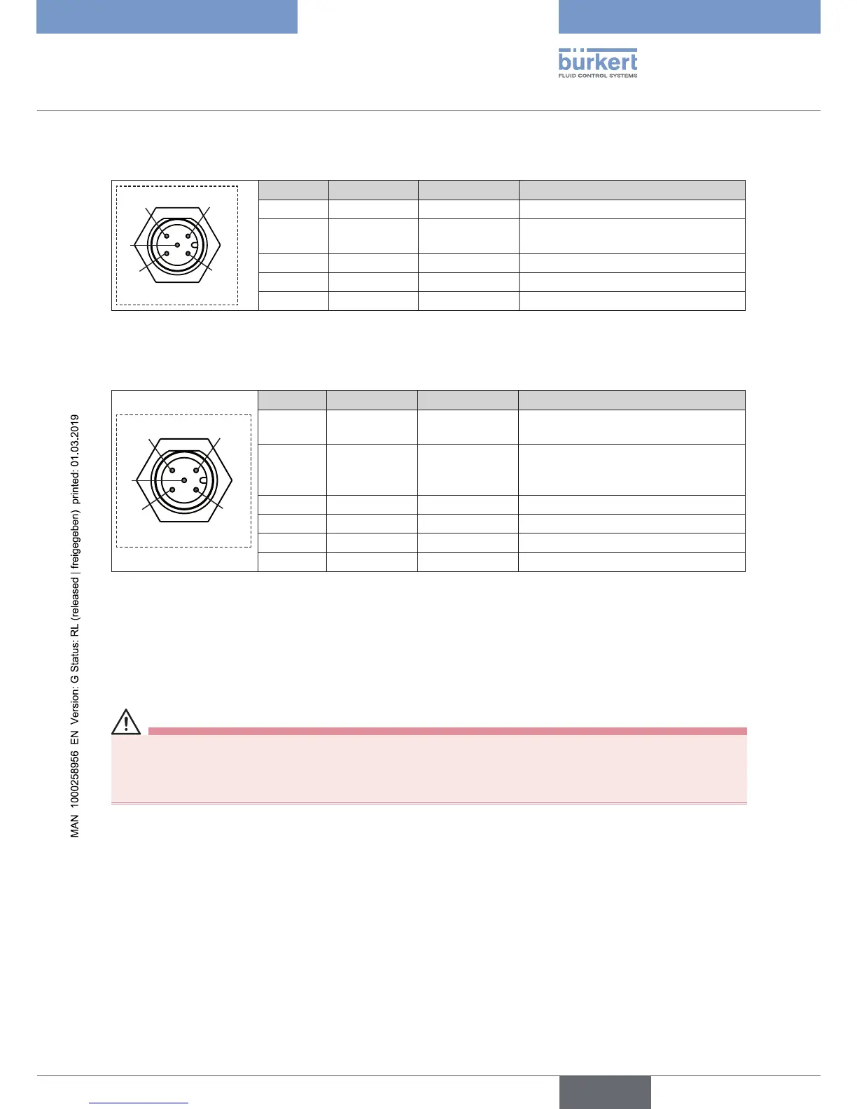
7.2.4.3 Digital version, circular connector M12, 5-pole
3
1
2
4
5
Pin Wire colors
*
Configuration External circuit
1 Shielding
2 red Supply + 24 V DC ±10 %, max. residual ripple
10 %
3 black GND GND
4 white CAN high CAN high
5 blue CAN low CAN low
* The indicated wire colors refer to the büS cables which are available as accessories.
7.2.4.4 Digital version, socket M12, 5-pole
3
1
2
4
5
Pin Wire colors
*
Configuration External circuit
1 brown Sensor supply
+
24 V DC ±10 %, max. residual ripple
10 %
2 white Actual value
input
sensor +**
0...20 mA / 4...20 mA / 0...5 V / 0...10
V / Frequency (Pulse +)
3 blue GND GND
4 black GND GND (Bridge to GND Pin 3)
5 grey Not assigned Not assigned
Body Shielding -
* The indicated wire colors refer to the connection cable, order no. 559177, available as an accessory.
** A PNP sensor must be used.
7.3 DIP switch settings (analog version only)
DANGER!
Risk of injury due to electrical shock.
▶ Before opening the actuator cover, switch off and isolate the power supply to prevent reactivation of the device.
▶ Observe applicable accident prevention and safety regulations for electrical equipment.
Although the factory settings are ideal for most applications, the settings can be adjusted with DIP switches. The
DIP switches can be set to “ON” or “OFF” position depending on the factory order code.
The DIP switches are accessible on the electronic PCB by opening the actuator cover.