16
Installation
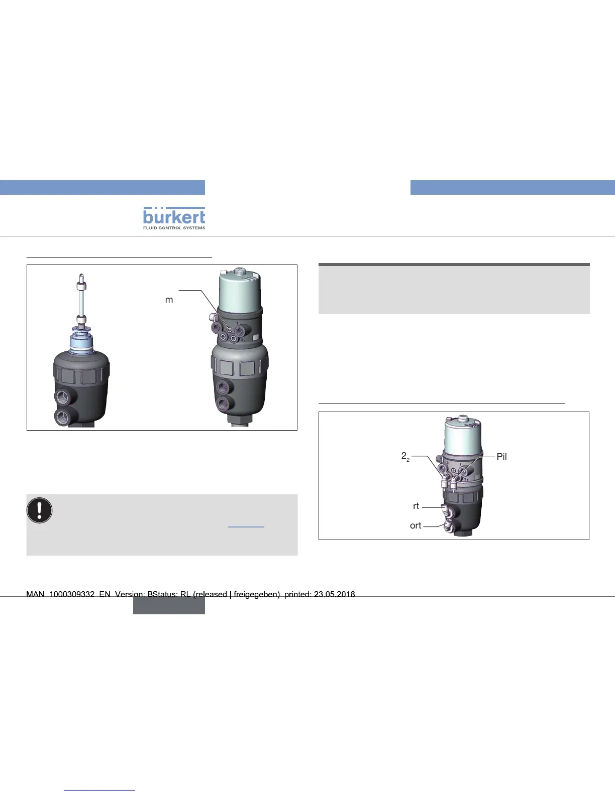
2. InstallationofthePneumaticControlUnit
Fastening
screws
max.0.5Nm
Fig. 12: Installation of the Pneumatic Control Unit, series 20xx
→ Push the Pneumatic Control Unit onto the actuator.
→ PressthePneumaticControlUnitallthewaydownasfarasthe
actuator and turn it into the required position.
EnsurethatthepneumaticconnectionsofthePneumatic
ControlUnitandthoseoftheactuatoraresituatedpref-
erablyverticallyoneabovetheother(see“Fig.12”).
If they are positioned dierently,longer hoses may be
requiredotherthanthosesuppliedintheaccessorykit.
NOTE!
Too high torque when screwing in the fastening screw does
not ensure degree of protection IP65 / IP67.
▶ Thefasteningscrewsmaybetightenedtoamaximumtorque
of0.5Nmonly.
→ Attach the Pneumatic Control Unit to the actuator using the two
sidefasteningscrews.Indoingso,tightenthefasteningscrews
hand-tightonly(maximumtorque:0.5Nm).
3. Installationofthepneumaticconnectionontheactuator
Pilot air outlet 2
1
Lower pilot air port
Upper pilot air port
Pilot air outlet 2
2
Fig. 13: Installation of the pneumatic connection, 20xx series