12
Installation
7. INSTALLATION
Only for Pneumatic Control Unitwithout pre-assembled
processvalve.
7.1. Safety instructions
DANGER!
Risk of injury from high pressure in the equipment/device.
▶ Beforeworkingonequipmentordevice,switchothepressure
anddeaerate/drainlines.
Risk of electric shock.
▶ Beforereachingintothedevice,switchothepowersupply
andsecuretopreventreactivation.
▶ Observeapplicableaccidentpreventionandsafetyregulations
forelectricalequipment.
WARNING!
Risk of injury from improper installation.
▶ Installationmaybecarriedoutbyauthorizedtechniciansonly
and with the appropriate tools.
Risk of injury from unintentional activation of the system and
an uncontrolled restart.
▶ Securesystemfromunintentionalactivation.
▶ Followinginstallation,ensureacontrolledrestart.
7.2. Installation on process valves of
series 21xx
Procedure:
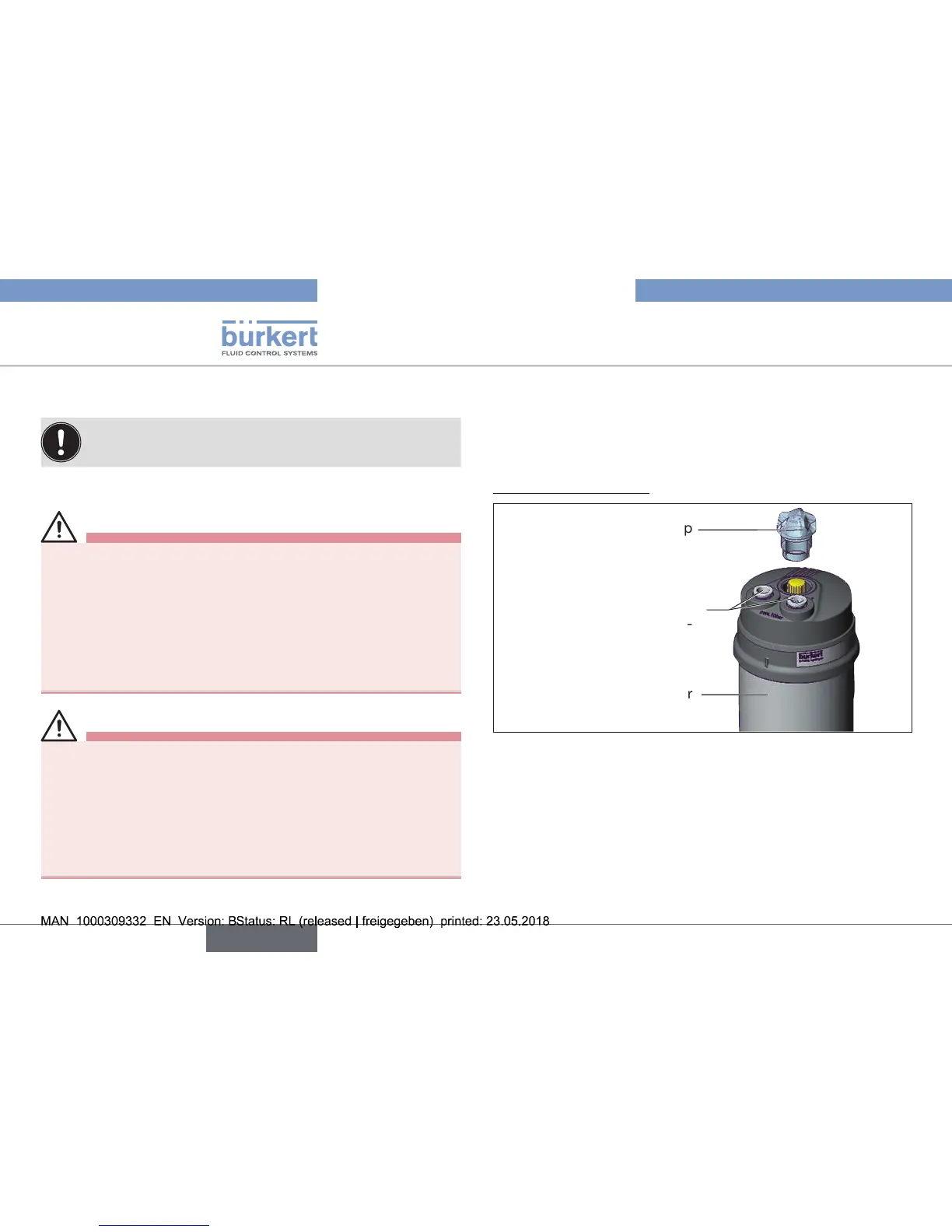
1. Install switch spindle
Transparent cap
Actuator
Pilot air ports
(plug-in hose con-
nectors with collets or
threaded bushings)
Fig. 6: Installation of the switch spindle (1), 21xx series
→ Unscrew the transparent cap on the actuator and unscrew the
position display (yellow cap) on the spindle extension.
→ For version with plug-in hose connector, remove the collets
(whitenozzles)frombothpilotairports(ifpresent).